
When collecting field data, the Field-to-Finish process can be used to draw the points with distinct layers, symbols and other settings based on the point description. Each point description is looked up in the Field-to-Finish code table which defines the layer, symbol and other properties for that description. The code definition can also be used to draw linework between the points. This code table is created using the Field to Finish command in the COGO menu. Codes can be alpha, numeric or alphanumeric. The Carlson Field data collection functions Point Store and AutoPoints at Interval can use a Field-to-Finish code table.
Field-to-Finish - Use Code Table ...
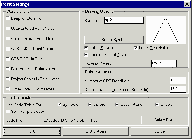
For Field-to-Finish mapping while collecting field data, go to Configure Field, select Point Settings. Under the Field-to-Finish heading check the boxes to the right of Use Code Table For. This activates Field-to-Finish so that points stored with descriptions that are defined as codes in the code table are drawn using the code symbol, description, linetype and layer.
Field-to-Finish - Code File
The currently active code table file is displayed next to
Code File. Only one Field-to-Finish code table is active at a
time. Several code tables can be created for different clients or
applications.
Use the Select File button to set which code file is active.
Selecting a Code
Both functions Point Store and Auto Points at Interval can use Field-to-Finish capabilities. Each of these data collection functions can display a list of the codes from the currently active Field-to-Finish code table. This alleviates you from having to guess code abbreviations. When you pick Code or press F7, a summary of the currently active code table appears. Use Page Down or Page Up to scroll quickly though the code table. Use the Up or Down arrow keys to highlight the code description desired and double click or press Enter to select. If you already know the code, you can just type it in the Desc field.
Field-to-Finish - Options (F6)
If you are using the Point Store or Auto Points at Interval functions, you can change your Field-to-Finish settings by clicking Options or hitting F6. This brings up the Point Settings window. You can toggle the Field to Finish options on or off, or you can select a different code table. You can also change the default point settings here. All of this can be done without leaving Point Store or Auto Points at Interval.
Field-to-Finish - Editing the Code Table
The code table can be displayed using the command
Field to Finish under the COGO menu.
Each line corresponds to a code. All of the code's parameters (layer,
symbol type, description,
size,
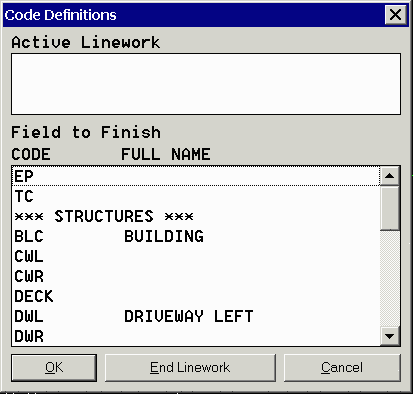
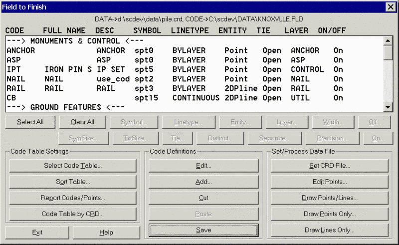
linetype) are controlled from here. Clicking on a code will bring up a window which will let you change the settings for this code. New codes can be added using the Add button on the code table.
Field to Finish - Linework
Linework includes all mapping by 2D or 3D polylines with line and arc segments. The Field-to-Finish code table controls the linetype, color and layer for all linework. It does not control where polylines, lines or arcs start or end. Starting and ending linework is controlled directly in Carlson Field's data collection commands Point Store and Auto Points at Interval.
2D Polylines are always drawn at zero elevation. Their linetypes can be defined in the code table. A simple curve requires three points: a PC, one point on the curve and a PT. The simple curve is drawn as an arc. Complex curves can be shot using multiple points along the curve between the PC and PT. There is no upper limit to how many points can be used. Carlson Field does a Bezier fit to join all these points. The complex curve is actually drawn as a series of very short chords.
3D Polylines are a series of connected 3D points. All curved sections of 3D polylines are drawn as series of very short chords. Elevations of these chords are interpolated from the elevations of the curve endpoints. 3D polylines can be used as breaklines for surface modeling of curving curb lines, retaining walls or any other structure. Using Carlson Field's Triangulate and Contour command, operators can create a contour map in the field using the data they just gathered and thus check that no areas or breaklines lines are missing or incomplete prior to leaving the site.
Nesting Linework & Points
Both Point Store and Auto Points at Interval allow you to be drawing multiple polylines at the same time. Without ending your current line, you can start another line by simply changing the description code. As long as you didn't select End under Linework for your first line, you can come back to it later. Carlson Field will always recognize if a code next to Desc refers to a line currently active. If it does, Carlson Field continues that line to the new point. To stop a line from being active, you can choose End under Linework before storing the point number.
If two or more polylines are drawn in the same session using the same code, you must add a number after the code to differentiate between two lines. (e.g. EP, EP1, EP2...)
If you use the same point number twice, Carlson Field will allow you
to select a new number,
override the previous coordinates, or average the two measurements
together.
Field-to-Finish Quick Overview
Point Store - Steps to draw using Field-to-Finish:
1) Configure Field - Select the GPS or Total Station equipment in the first dialog.
2) In Configure Field->Point Settings, select the code table to be used. Enable "Use Code Table For" by checking "Symbols", "Descriptions", "Linework" and "Layers".
3) Initiate "Point Store" in Field.
4) Press F7 for the Code button to select the defined code "UP" from the Field-to-Finish code list.
5) Press F8 to start linework or check "Start" under linework .
6) Press F1 for the Read button to take a shot.
7) Press F2 for the Store button to store this point.
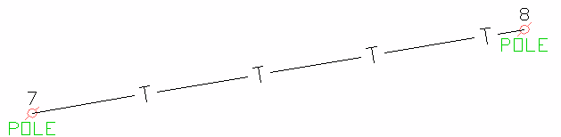
Now move to the next location and hit F1 then F2 again to repeat steps 6 and 7. Notice a line between points 7 & 8 draws with a "T" for telephone line and the symbol drawn is a utility pole symbol. The symbol, linework and layer are predefined for the "UP" code in the Field-to-Finish code table. If a line between the two points does not draw, simple click in the join box and a line is drawn between the two points.
Remark: In "Linework", after picking "Start", the next shot with the same description defaults to "Cont"(continue) automatically and the line continues to this next point. When finishing linework, you must select "End" to stop the linework. Linework for breaklines should always be 3D polylines with elevations, unless you select the "No Elev" option. 2D polylines are always drawn at zero elevation and their linetype is defined in the Field-to-Finish code table.
2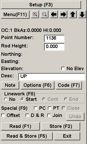 7
7
Special Characters and Conditions
When collecting points with additional description information besides the code, use a forward slash (/) after the code and before the additional description. All text after the forward slash is appended text that does not affect the code table (e.g. UP/#531, BLD/COR, PIPE/24", 14D/OAK ). When drawing the point in the CAD drawing, the forward slash disappears and UP/#531 will plot as POLE #531. The original code, with forward slash and appended text, is stored in the coordinate and raw file.
Mulitple codes are allowed in Point Store. In collecting a point such as a "T" intersection in a fence, the point can be collected once, but with two codes (seperated by a space) as the Desc (e.g. FP1 FP2). This also applies when storing a point that contains two or more distinct ground features (e.g. Edge Of Pavement and Catch Basin). Here also you can collect one point and store this point with two codes seperated by a space (e.g. EOP CB). The point plots twice: once in the EOP layer and a second time in the CB layer. The point is plotted on two layers in the drawing, but is stored only once in the coordinate file. Points collected in this fashion can have multiple symbols and have multiple lines drawn through them.
Undefined Codes
All points stored without descriptions or with descriptions not
stored in the Field-to-Finish
code table are drawn using the default Drawing
Options in Configure Field->Point
Settings.