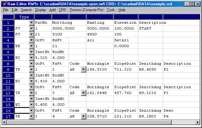
This program reads or creates a raw data (.RW5) file that contains various lines of data (records) that could be likened to a surveyor's field book. You can specify point coordinates, job information, notes, and the angles and distances that make up traverse or sideshots records. Once the raw data is created or read it can be processed/reduced to coordinates that are stored in the current coordinate (.crd; .cgc; .mdb; .zak) file.
The raw file can also be created or appended using the Locate Point, Traverse, Sideshot, and Inverse commands on the Cogo menu. To store the data inputs from these commands into a raw file, first toggle on the Raw File ON/OFF command on the Cogo menu. It is possible to always have the raw data file open to store data inputs. To enable this option, choose Configure from the Settings menu, then choose Survey Module, then choose General Settings. Turn on the Automatic Raw File toggle in this dialog.
The raw files created by TDS data collector programs are also compatible without conversion. The command Data Collectors on the Tools menu has options for reading other data collectors native file formats and converting them to raw data (.RW5) format. Within the raw data editor, the File menu includes an import menu for converting raw data from other formats.
When you select the Edit-Process Raw Data File command you are prompted to specify the name of the raw data (.RW5) file. The current coordinate file is used automatically. To change the current coordinate file, use the Set Coordinate File command in the Points menu before starting this command. If no coordinate file is current, the program will prompt you to set the current coordinate (.CRD) file.
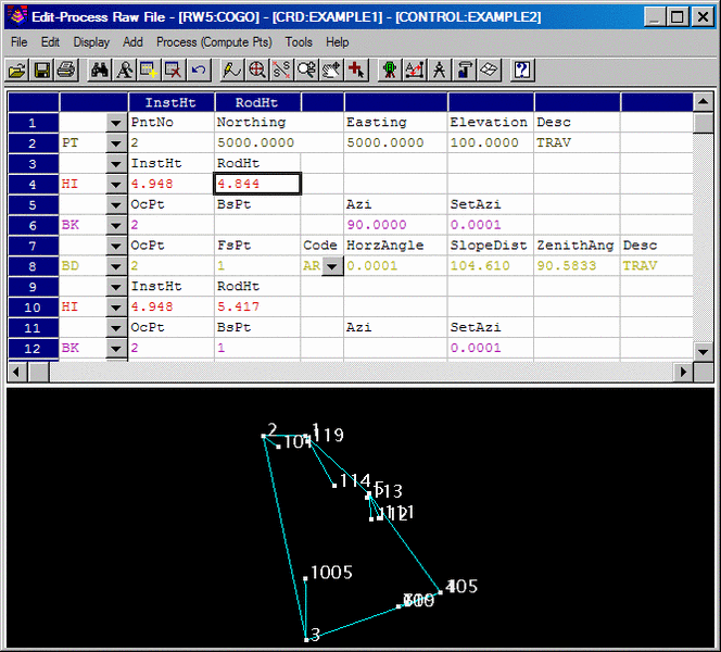
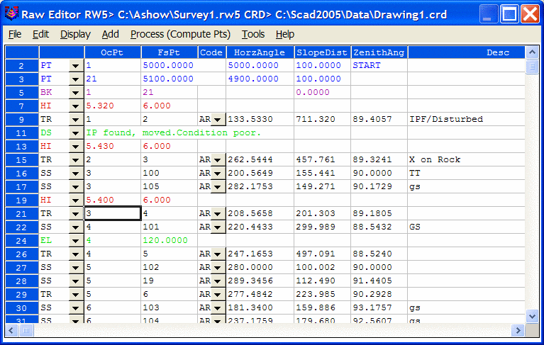
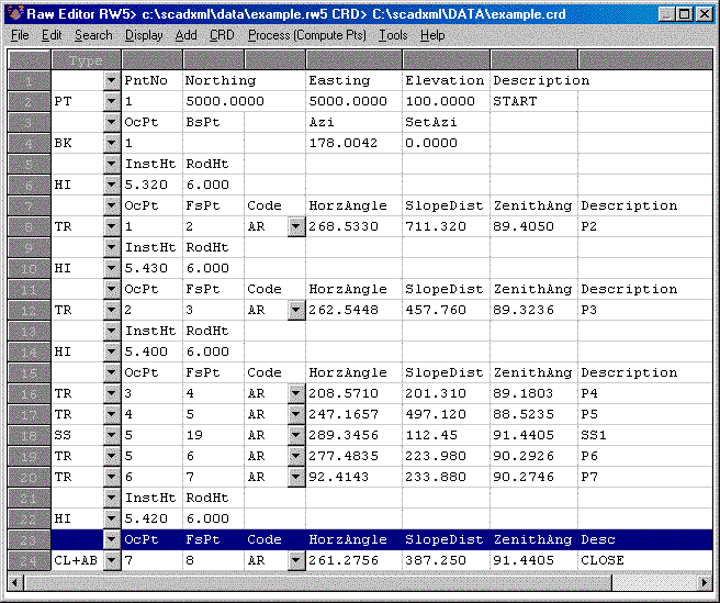
Edit-Process Raw Data File uses a spreadsheet for editing the
raw data as shown. Each row of the spreadsheet is represented by a
number located at the far left side of the editor. Various
messages and reports often reference possible problems with
the data by this row number. Each row
of the spreadsheet represents one record of data. There are 14 types of
data records. The type of
data record is shown in the first column. Different record types use
different numbers of
columns. Whenever the data record type changes between rows, a record
header is added to the
spreadsheet that describes each column of data in the following row. To
edit the raw data, simply highlight the cell and type in the new value.
To change the type of
record, pick on the down arrow in the first column and choose a new
data type from the list. To delete
a row, highlight any cell in the row and hit the Delete key or choose
Delete Row from the Edit
menu. Records can be added pressing the Insert key, pressing the down
arrow key from the last line
in the spreadsheet, or by choosing one of the add records from the Add
menu.
The different record types are described below.
TR (Traverse)
The traverse record contains the occupied point number, foresight
point number, angle
mode, horizontal angle, distance, vertical angle and description. When
processed, this record
will calculate and store the coordinates for the foresight point.
Traversing also moves the setup
by making the traverse foresight point the next occupied point and the
traverse occupied
point becomes the next backsight point. The different angle codes are
NE for northeast bearing, SE
for southeast, SW for southwest, NW for northwest, AZ for azimuth, AL
for angle left, AR for
angle right, DL for deflection angle left and DR for deflection angle
right. To set the angle code, pick
on the Code down arrow and choose from the list. The horizontal and
vertical angles should be
entered as dd.mmss. For example, 45.2305 is 45 degrees, 23 minutes and
5 seconds. The vertical angle
can be shown as vertical angle (0 degrees level), zenith angle (90
degrees level) or elevation
difference. The vertical angle mode is set in the Display menu. The
distance mode is also set in the
Display menu as either slope or horizontal distance. The description
field is used as the foresight
point description.
SS (SideShot)
The sideshot record is the same as the traverse record except that
sideshot does not move the setup.
HI (Instrument and Rod Height)
This record sets the instrument and rod heights used in elevation
calculations. This record
should precede any traverse and sideshot records that you want the
heights
applied to.
BK (BackSight)
The backsight record contains the occupied point number, backsight
point number,
backsight azimuth and the set azimuth. This record should precede any
traverse and sideshot records
that use this setup. If no backsight point is entered, the program uses
the backsight azimuth to
turn angles from. The Set Azimuth is the circle reading of the
instrument when sighting the
backsight. A Set Azimuth of zero is the default.
PT (Store Point)
The store point record consists of a point number, northing,
easting, elevation and
description. When processing, this data will be stored as a point in
the coordinate file. If the first Occupied point and/or the
initial Backsight point are not defined in the coordinate file set for
processing to, both points will need to be added to the rw5 file as PT
(Store Point) records.
DS (Description)
The description record is an additional note that appears in the
spreadsheet editor and printouts. This record can contain various
information that is recorded in data collectors during field
operations. This data can vary from user, temperature and general
data to each line of data associated with "Set Collection". When
"Sets" of data collected using various brands of data collection
software is converted/imported into the raw editor, the actual
measurements made during the spinning of the angles and distances are
recorded as DS records and the mean value of the angle and distance is
recorded as a SS record. DS records are not used in processing.
CL (Closing Shot)
The closing shot record is the traverse record where the foresight
point is the closing point for
the traverse. This record is used by the adjustment commands in the
Process menu. There should
be only one CL record in each Traverse loop (Name Record) in the raw
file. If there is no CL
record, the process adjustment routines will prompt for which shot is
the closing shot. The closing shot can also be define in the
field by using special codes defined in the Open Settings found under
the File pulldown within the editor. Please refer to the "Open
Settings" documentation below for more information on these
codes.
AB (Angle Balance)
The Angle Balance record is the measurement data observed that
closes the angles of the traverse. Typically this record is the
measurement data recorded from the closing shot to the initial
backsight point. The backsight could be either external or
internal to the traverse. Angle Balance
routine in the Process menu
uses this record and compares the angle between the occupied point and
foresight
point of this record with a
user-specified reference angle. There should be only one AB record in
the raw file. If there is no AB
record, then the Angle Balance routine will prompt for which shot to
use as the angle balance.
CL + AB (Closing Shot and Angle Balance)
This record is used as both the closing shot and angle balance
records.
FD (Foresight Direct)
The foresight direct is a traverse record used in a direct and
reverse set. When the program
finds one the of direct-reverse measurement records, it will look for
the other three records to
complete the set.
FR (Foresight Reverse)
The foresight reverse is a traverse record used in a direct and
reverse set.
BD (Backsight Direct)
The backsight direct is a traverse record used in a direct and
reverse set.
BR (Backsight Reverse)
The backsight reverse is a traverse record used in a direct and
reverse set.
EL
(Elevation Only)
This record sets the elevation in the CRD file for the specified
point
number. Often used when an existing point with good vertical
control is being traversed through. Using this record type for
the point would keep the elevation from changing on the existing point
regardless of the measurement data.
AZ
(Azimuth Only)
Applies to SurvNET, the optional Network Least Squares analysis and
adjustment routine.
CSE
(Control Standard Error)
Applies to SurvNET, the optional Network Least Squares analysis and
adjustment routine.
SSE
(Set-up Standard Error)
Applies to SurvNET, the optional Network Least Squares analysis and
adjustment routine.
MSE
(Measurement Standard Error)
Applies to SurvNET, the optional Network Least Squares analysis and
adjustment routine.
NAME (Traverse Name)
This record acts as an identifier for the group of records that make
up a traverse. All the
records after the NAME record belong to that traverse up to the next
NAME record or the end of the
file. This record allows you to have multiple traverses in one raw
file. When running one of the
Process commands, the program will bring up a list of all the traverse
names. Simply choose which
traverse to process. If you have only one traverse in the raw file,
then you don't need the NAME record.
GPS
This record
contains the Latitude and Longitude of a point as measured by GPS
surveying equipment using Carlson SurvCE data collection
software. This record has additional information tied to it such
as localization files, geoid files, coordinate projection systems
etc. This record has its own processing routine in the Process
pulldown within the editor. Processing procedures are discussed
in the Process (Compute Pts) pulldown documentation.
Save
This saves
the rw5 file. If the file hasn't been named you will be prompted
for the file name and the location to save the file. After you
preform the first save, this command acts as a quick save and saves the
file to the name and location specified during the initial saving of
the file.
Save As
This
command saves the file and always prompts for file name and location to
save.
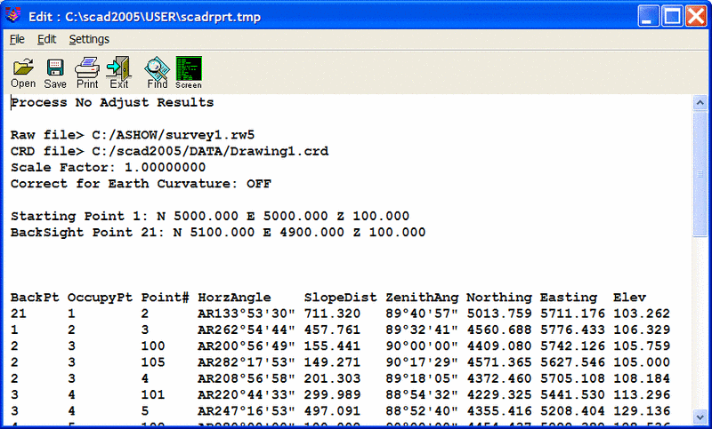
Print
This command outputs the raw data file to the Carlson
Standard Report Viewer. From here, you can print the report,
draw it in the drawing or save it to a file. See
Standard Report Viewer for more information. See example
printout:
Raw File> c:\scadxml\data\survey.rw5
CRD File> c:\scadxml\data\survey.crd
   Note
   Survey Example
   PntNo   Northing Easting   Elevation Desc
   1       5000     5000    100       START
   OcPt    BsPt     SetAzi
   1
   InstHgt RodHgt
   5.32    6.0
   OcPt    FsPt     HorzAngle SlopeDist ZenithAng Desc
TR 1       2     AR 268.5330  711.420   89.4050   P2
   InstHgt RodHgt
   5.43    6.0
   OcPt    FsPt     HorzAngle SlopeDist ZenithAng Desc
TR 2       3     AR 262.5448  457.760   89.3236   P3
   InstHgt RodHgt
   5.4     6.0
   OcPt    FsPt     HorzAngle SlopeDist ZenithAng Desc
TR 3       4     AR 208.5710  201.310   89.1803   P4
TR 4       5     AR 247.1657  497.120   88.5235   P5
TR 5       6     AR 277.4835  223.980   90.2926   P6
TR 6       7     AR  92.4113  233.880   90.2746   P7
   InstHgt RodHgt
   5.42    6.0
   OcPt    FsPt     HorzAngle SlopeDist ZenithAng Desc
TR 7       8     AR 261.2756  387.250   91.4405   CLOSE
SS 7       19    AR 289.3456  112.450   91.3423   SS1
Import
These routines convert raw data from other formats into the current
Carlson RW5 format.
The converted raw data will be added to the end of any existing data in
the editor. In many cases,
the raw data file to import can be downloaded directly from the data
collector or instrument using
the Data Collectors command. The following supported formats
(along with their standard
file extension) are listed here. Some Sample File Formats are listed at
the
end of this section.
C&G (.CGR;.RAW;.TXT;*)
CalTrans (.DMP)
Carlson (.RW5)
Fieldbook (.FBK): From Softdesk or Land Development Desktop.
Geodimeter (.OBS; .RAW; job;*)
LandXML (.XML)
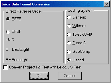
Leica (.GSI; .RAW; GRE): This reads the Leica raw file in
Wildsoft, Liscad,
10-20-30-40, C&G, or GeoComp format. There are options to specify
direct-reverse
shot order if any and to convert from International Feet to Leica US
Feet.
Maptech (.FLD)
MDL Laser (.CDS)
Nikon (.TRN; .RAW)
PC Cogo (.BAT)
SDMS (.prj;*)
SMI (.RAW)
Sokkia SDR (.SDR; .RAW;*)
SurvCOGO (.RAW or .TXT)
Survis (.RAW)
TDS (.RW5; RAW)
Topcon (raw;*)
Trimble (.dc)
3TA5 (.TXT)
Zeiss (.DAT)
Export
These routines convert the Carlson raw data (.RW5) file to other
formats. The following
file formats are supported.
CalTrans (DMP)
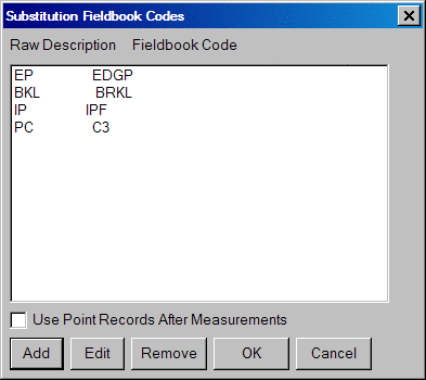
Fieldbook (.FBK): This export routine provides an option to "Setup Fieldbook Codes". This allows the user to substitute the raw description contained in the rw5 file with the fieldbook code used in AutoDesk Land Desktop.
FL DOT (.OBS)
GPS Data (.TXT;*)
Land XML (.XML)
MOSS (.MOS)
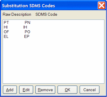
SDMS (.PRJ) This export routine provides an option to "Setup SDMS
Codes". This allows the user to substitute the raw description
contained in the
rw5 file with the SDMS codes used in SDMS program.
Sokkia (.SDR)
TDS (RW5;RAW)
VA Dot (TOP)
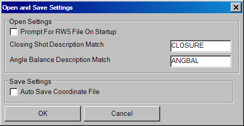
Open
Settings
This option allows
for defining codes that represent the closing shot and angle balance
shot of a traverse. These codes can be entered in the description
of a point while in the field. When the rw5 is opened in the raw
file editor, the measurement data containing the closing shot code will
be set to a CL record and the measurement data containing the angle
balance code will be set to an AB record. This allows for quick
processing of the survey data and saves the time spent setting up the
file for processing.
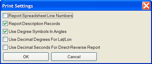
Print
Settings
Provides
control of various options for printing the rw5 file in
the Standard Report Viewer.
Exit
Exits the raw file editor.
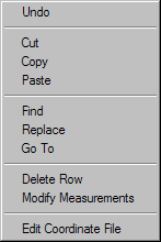
Undo: This
command undoes the
last data entry or the last copy, cut or delete command performed on
keyboard entered data only. This will not undo a change to the
Type or Code columns, nor a cut or copy command to a row.
Cut: Standard windows cut
command. Removes data from editor and places it in the windows
clipboard.
Copy: Standard windows copy
command. Copies selected data to windows
clipboard.
Delete: Deletes
selected data or row of data. Will not delete headers if
data is present below the header.
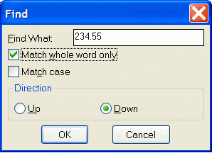
Find: Tool to search
and find a particular word, letter, numeric value or a
combination of all. Provides options to Match whole word only
and/or case. Allows for a up or down directional search from the
active cell in the editor.
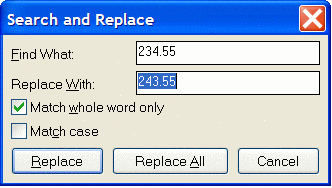
Replace: Tool to search
and replace a particular word, letter, numeric value of
a combination of all. Options to Match whole word only and /or
case is provided for the search criteria. Provides further
options to Replace individual items one at a time or to Replace All.
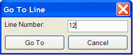
Go
To: Tool
to advance the focus of the active cell to a
specified line number.
Delete
Row: This
command deletes the row containing the active
cursor or cell. You can delete a row by placing the cursor in any
of the cells in the row that you wish to delete, or by picking on the
row number at the far left of the editor.
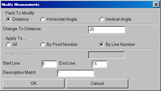
Modify
Measurements:
This option allows for a change in distance,
horizontal angle
or vertical angle by a specified amount for the entire file or for a
specified
point number or line number range.. To modify a measurement,
choose which field to modify, enter the
change in either distance or angle in dd.mmss format. Next choose
how
to apply the modification. If all is selected, the change will be
applied
to all records in the specified field. If By Point Number is chosen,
enter the point number or range of
numbers
in the Range of Points field. If by
Line Number is chosen, then define the area for the change by
specifying the
Starting and Ending line.
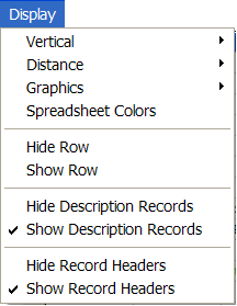
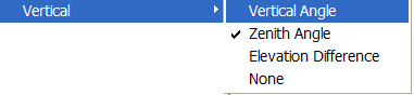
Vertical: The options contained in this menu allow for specifying the type of vertical measurement information you will input or is contained in the rw5 file. The Vertical Angle selection assumes the barrel or scope of the instrument is level when reading 0 (zero). With this setting, the vertical component of a measurement record will have a header of VertAng. The Zenith Angle selection, most commonly used, assumes the barrel/scope to be level when reading 90. Using this setting results in a header of ZenithAng. Elevation difference displays the elevation difference between the occupied and foresight points. If the Distance option is specified as Slope, this elevation difference will be used to calculate the horizontal distance of the measurement. The header for this record is ElevDiff. The None selection assumes all distances are horizontal distances and removes the vertical component for a measurement from the editor. Switching modes can be performed at any time.
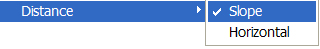
Distance: This option
controls the display of either Slope or Horizontal
Distances. Changing the display results in the distance data
adjusting to reflect the correct value for the selection
made. The Vertical data, VertAng, ZenithAng or VertDiff, is
used to convert the distance value when changing this display option.
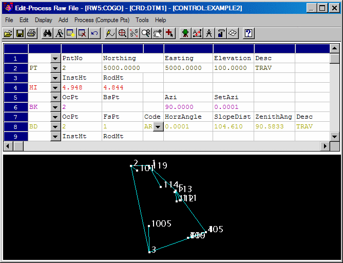
Graphics: The Raw Data Editor uses an optional graphics window to display the points and traverse lines in real time. As data is entered or edited, the graphics window will be updated to show the configuration or new configuration of the traverse. The option of whether to show sideshots is also available. When a cell is selected, the traverse or sideshot line in the display window will change to the color yellow for a graphical reference. The graphics window is toggled on or off from the Display | Graphics Window menu inside the raw file editor.
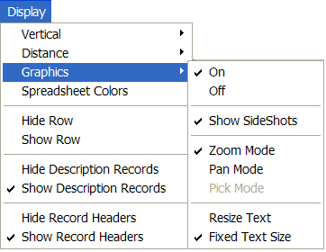
Graphics>On: Turns the graphics window on.
Graphics>Off: Turns the graphics window off.
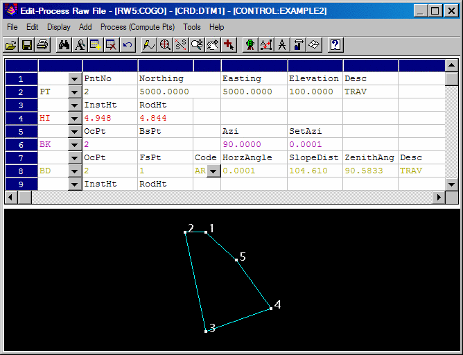
Graphics>Show Sideshots: Controls the display of the sideshot data in the graphics window. Figure 1 shows the graphics window with sideshots on. Figure 1A shows the graphics window with sideshots off.
 |
| Figure 1 Sideshots On |
 |
|
Figure 1A Sideshots Off |
Graphics>Zoom Mode: Within the graphics window, real time zoom is available. To zoom in press and hold the left mouse button and drag in the direction of the + symbol. To zoom out, press and hold the left button and drag in the direction of the - symbol.
Graphics>Pan Mode: Real time pan is available within the graphics window. To pan, set the graphics window to pan mode, then press and hold the left mouse button and then drag to desired position.
Graphics>Resize Text: With the this option on the text becomes smaller/larger in the view when you zoom in/out.
Graphics>Fixed Text Size: With this option on, the text stays a fixed size while zooming in and out.
Spreadsheet Colors: This option allows for the assignment of colors to record types. To change/define the color for a particular record, select Spreadsheet Colors from the Display pulldown within the raw editor. From the Color Settings dialog select the record to edit by clicking on the select button next to the desired record.
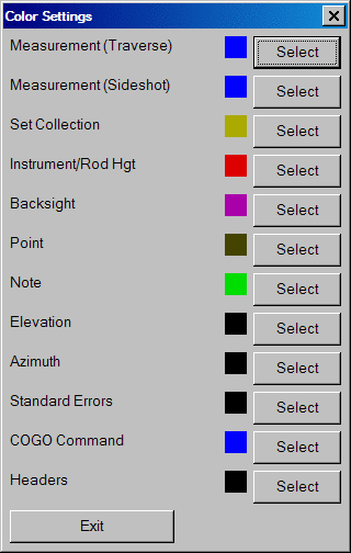
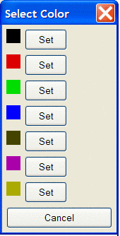
The color slide beside the select button shows the current setting for the record. After selecting the record, the Select Color dialog box will be display. Select the Set button next to the desired color for the record.
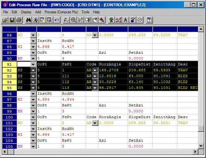
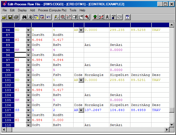
Display>Hide Row: This option allows for hiding single or multiple rows. This could be used to prevent crucial information from being accidently altered during editing of data or data entry. Hiding a record does not exclude it from processing. To hide a record click on the row number at the far left of the editor. The entire row of data will highlight, now select the Hide Row option. Multiple rows or data can be selected by selecting the first row of data to hide then while holding down the shift key on the keyboard, select the last row to hide. All rows in between these two selections will be highlighted, now select Hide Row. When a row or rows of data are hidden, the row numbers will reflect the hidden rows. For example, Figure 2 below shows a multiple selection of rows 10-17 to hide. Figure 2A shows the editor with the rows hidden. Notice that the row numbers indicate hidden rows by showing a gap from rows 9-18.
 |
| Figure 2 |
 |
| Figure 2A |
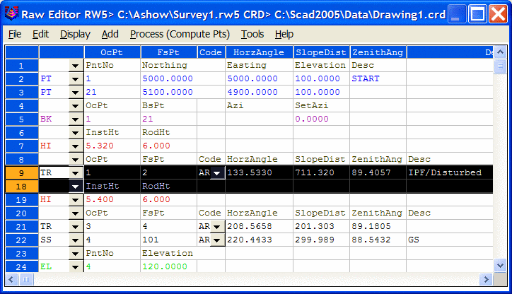
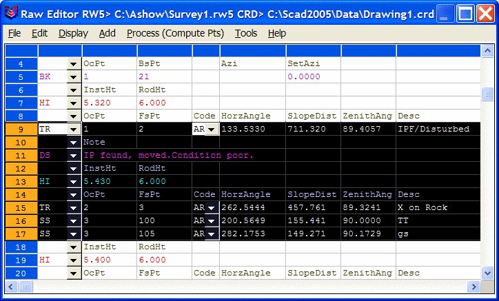
Show Row: This option shows rows that have been hidden. To show hidden rows, the row above the first hidden row and the row below the last hidden row must be selected by using the shift key selection method described in Hide Row above. After selecting the appropriate rows, select the Show Row option. Figure 2B shows the selection of rows 9 & 18 in order to show the hidden rows 10-17. Figure 2C shows the editor after the Show Row option has been selected.
 |
| Figure 2B |
 |
| Figure 2C |
Hide Description Records: This option controls the visibility of the Description records contained in a rw5 file. The description record is an additional note used to store useful information in addition to typical point data. Sometimes these records clutter the raw file and make it hard to review actual survey data. The ability to control the description record visibility is a useful tool when reviewing survey data.
Show Description Records: This option shows (unhides) description records contained in the rw5 file.
Hide Record Headers: This option hides the in-line headers such as the PntNo, OcPt, FsPt, etc. The editor contains "Smart Headers" that changes with the type of data that is in the active row. These headers are not in-line and are always displayed at the top of the editor. Figure 2D shows the editor with the record headers hidden and the Smart Header active. Row #21 contains the active cell, the automatic header at the top of the editor shows traverse (TR) record headers.
 |
| Figure 2D |
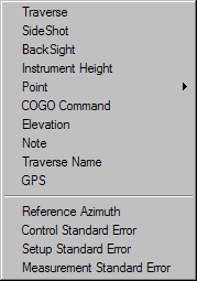
Traverse: Adds a
traverse record (TR) to the spreadsheet editor. The new
record will be insert above the row that contains the active cell
unless this row is the last row in the file. If so, you will be
prompted to insert above or below the current row.
SideShot:
Adds a sideshot record (SS) to the spreadsheet editor. The new
record will be insert above the row that contains the active
cell unless this row is the last row in the file. If so, you will
be
prompted to insert above or below the current row.
Backsight:
Adds a backsight (BK) to the spreadsheet editor. The new record
will be insert above the row that contains the active
cell unless this row is the last row in the file. If so, you will
be
prompted to insert above or below the current row.
Instrument
Height: Adds an instrument height (HI) record to the
editor. This record contains both the instrument and rod height
setting.
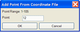
Point:
Adds a point (PT) record to the editor. Provides options to
either add a Blank Point Record or Import From Coordinate File.
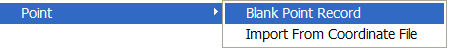
Inserting a blank record allows for manual input to define the
coordinates for the point. Import From Coordinate File imports
the coordinate values from an existing point or range of points
contained
in the coordinate file. Enter the point number or range of points
and select OK. The points will be read into the rw5 file at the top
of the file.
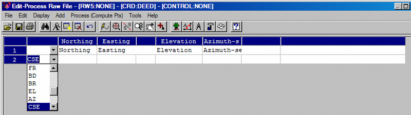
COGO Command: Adds quick COGO command entry functionality to the Raw File editor. Once a dropdown function is chosen within the spreadsheet, the appropriate column heading titles and cell descriptions are filled in. This first COGO Command figure below shows the result of choosing the COGO function CSE, which represents the record type Control Standard Error.
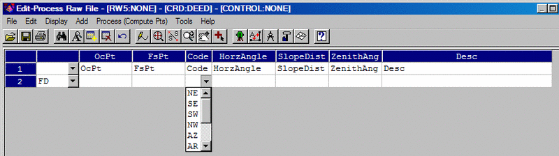
This second COGO Command figure below
shows the result of choosing the COGO function FD, which represents the
record type Foresight Direct. Note the the changed column headings.
Many other record types may be chosen, as seen listed in the dropdown
cells.
Elevation: Adds an elevation (EL) record to the editor. The new record will be insert above the row that contains the active cell unless this row is the last row in the file. If so, you will be prompted to insert above or below the current row.
Note:
Adds a note (DS) record to the editor. Note records need to be
added below the measurement record containing the foresight point that
the note is intended for.
Traverse Name: Adds a traverse name (Name) to the editor. The new record will be insert above the row that contains the active cell unless this row is the last row in the file. If so, you will be prompted to insert above or below the current row.
GPS:
Adds a GPS record to the editor. The new record will be insert
above the row that contains the active
cell unless this row is the last row in the file. If so, you will
be
prompted to insert above or below the current row.
Reference
Azimuth: Applies to SurvNET, the optional Network Least
Squares analysis and
adjustment routine.
Control Standard Error: Applies to SurvNET, the optional Network Least Squares analysis and adjustment routine.
Setup Standard Error: Applies to SurvNET, the optional Network Least Squares analysis and adjustment routine.
Measurement Standard Error: Applies to SurvNET, the optional Network Least Squares analysis and adjustment routine.
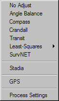
Process (Compute Pts) Menu
This menu contains tools to process raw data by various
methods. The calculated coordinates, and notes if specified, are
stored to the active specified coordinate file. The coordinate
file can be specified using Set
Coordinate File, under the Points
pulldown within the drawing screen, or from the Tools menu of the
editor, discussed later in this section. The options for processing are
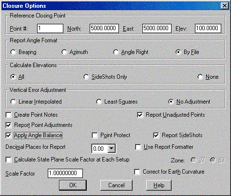
specified within either the Process Options dialog box or the Closure
Options dialog box, depending upon . This dialog box is
displayed before processing data, using any of the available methods,
with the exception being the Least Squares method.
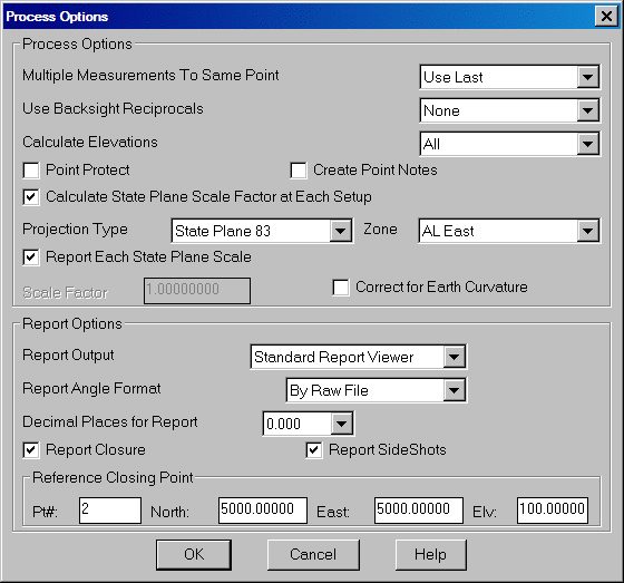
Multiple Measurements To Same Point: This option sets
the method of how to handle multiple measurements to the same
point. There are three available options, Use Last, Average or
Use First. Use last uses the last measurement to calculate
the position of the point. Average uses the average of all
the measurements for the position calculation and Use Last takes the
last measurement to the point as the data to use.
Use Backsight Reciprocals:
The Backsight Reciprocal options treat reciprocal measurements
"special". A foresight to point 15 from a setup on 14, followed
by a backsight from 15 to 14, makes a pair of "reciprocal"
measurements. The backsight "reciprocal" measurement can be
ignored for its impact on recalculating the occupied point (None
Option), or the elevation of component of the reciprocal measurements
can be averaged (Average Elevation option), or both the elevation and
distance can be averaged (Average Elev & Dist) to recalculate the
setup (occupied point) coordinates.
Calculate Elevations:
This option determines whether the elevations of the points will be
calculated and written to the coordinate file. Options of whether
to calculate All elevations or just the Sideshots Only are provided.
Direct-Reverse Vertical Angles: Specify whether to balance all or process the direct-reverse shots and use only the foresight direct shot.
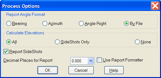
Report Angle Format: Specifies the angle format for the report. The By File option makes the report use the angle format in the raw data (.RW5) file.
Calculate Elevations: This option controls which point elevations will be calculated. For example, if the traverse point elevations have already been adjusted and you need to recalculate the sideshot elevations, then use the SideShots Only option.
Report SideShots: Specify whether to include the sideshot data in the process results report.
Point Protect: This option will check the coordinate (.CRD)
file for existing point data
before processing. If the foresight point number for any traverse or
sideshot record already is a
stored coordinate in the coordinate (.CRD) file, then the program shows
a list of conflicting point
numbers. You can either continue processing and overwrite the
coordinate (.CRD) file coordinates with
the calculated raw file coordinates or cancel the processing to go back
to the editor to change
foresight numbers.
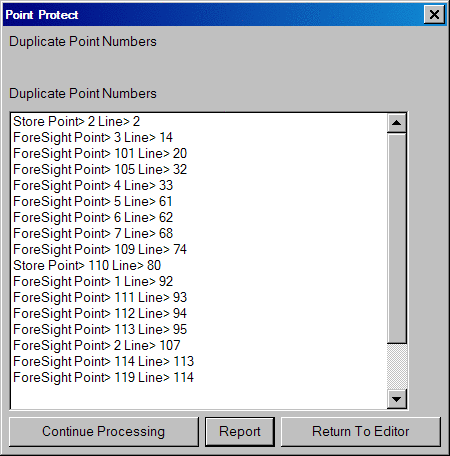
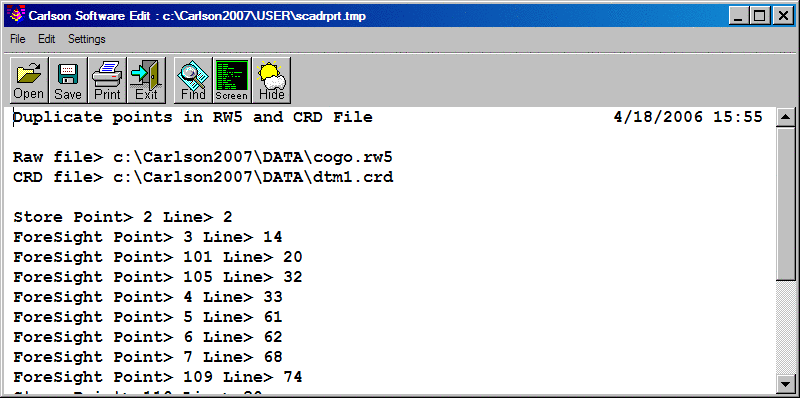
A report of the conflicting point numbers can be generated to the
standard report viewer in Carlson by selecting the Report option on
the Point Protect dialog box. From the report viewer, the report
can
then be printed, sent to the screen or saved to a file.
Create Point Notes: This option will generate a note (.NOT)
file named after the coordinate file.
The note file contains additional descriptions for points. With this
option active, the text from all
note records (DS records) will be stored to the note file for the
foresight point number preceding the
note records.
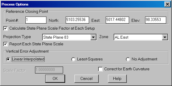
Calculate State Plane Scale Factor at Each
Setup: This option will calculate a scale factor for
each TR and SS record. This scale factor is calculated as the average
of the scale factors at the
occupied and foresights points. At these points the scale factor is
calculated as the state plane grid
factor multiplied by the elevation factor which is the earth radius
divided by the elevation plus the earth radius [SF = Grid
Factor * (Earth Radius / (Elevation + Earth Radius))]. In
order to calculate these state plane scale factors, the traverse
coordinates must be in state
plane coordinates. When this option is selected, the program will
prompt for the state plane zone to use. The Datum to use, NAD 27
or 83, must also be selected. This selection option becomes
available after selection the Calculate State Plane Scale Factor at
Each Setup option.
Report Each State Plane Scale: This
option becomes available if the Calculate State Plane Factor at
Each Setup has been selected. With this option on, the scale
factor at each point will be shown in the process results report.
Scale Factor: This value is multiplied by the slope distance
for the traverse and sideshot records.
Correct for Earth Curvature: This option adjusts the
calculated points for the effect of the
Earth's curvature. Typically this adjustment is small and adjusts the
elevation more than the horizontal.
Report Output: There
are three report output options contained in the raw editor, the Standard Report Viewer,
the Custom Report
Formatter and the Tabular Report Viewer.
Each is documented below.
The Standard
Report Viewer
is the default report viewer throughout the program. Any routine
that generates a report has this option and the data contained in the
report depends upon the routine executed. The report viewer is
also a text editor. It allows for addition and deletion of text
in order to customize the report for printing or for saving to a
particular format for a file. Options to print, send to the
screen in the drawing window as text or save to a file are
available.
The Custom
Report Formatter allows for customization of the process
results by selecting the fields and the layout of the fields to
display. The settings can be saved to a format name and recalled
when needed. Options to Delete, Export and Import saved Formats
are also available.
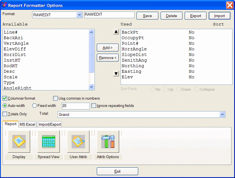
To create a report, select data from the Available list and then
select the Add button. This will populate the Used field with the
selected data. Standard window selection methods can be used when
selecting the data to report. Holding the ctrl key while
selecting data allows for making random selections. Holding the
shift key while selecting data will select the first item picked, last
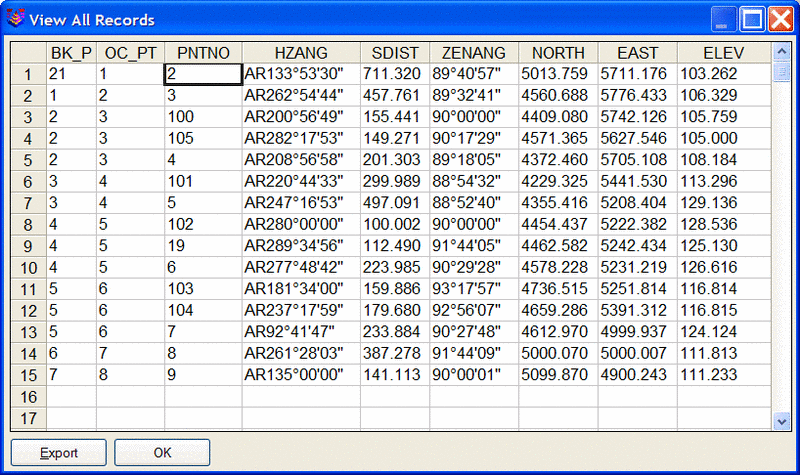
item picked and all items between. With Columnar format
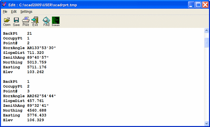
"checked" on, the report is displayed as follows:
With Columnar
Format off, the report is displayed as follows:
The Auto-Width
option displays each column width based upon the data contained within
it. The Fixed
Width option allows for a specified column width for each field
of data.
Totals Only: This
option does not apply to the process raw data results but is
useful in other reports to report total values of certain data.
Total: This field reports totals for
various combinations of the attributes selected to report.
The icons and tabs at the bottom of the Report Formatter Options
dialog box provide display options, Import/Export options and User
Attribute creation, editing, importing and exporting.
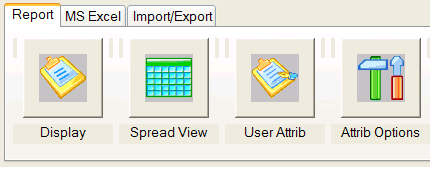
Report Tab:
Display: Displays the selected data and field arrangement.
Spread View: Displays
the selected data in MS Excel format.
User Attrib: This
option allows for the creation of attributes that allows for
mathematical calculations. The math functions allowed are
addition, subtraction, multiplication and division. This option
is
detailed further in the General section of this manual.
Attrib Options: This option allows for the addition, editing importing and exporting of pre-defined and user attributes. This option is detailed further in the General section of this manual.
MS Excel Tab: This
tab contains options and settings for exporting the report to MS Excel.
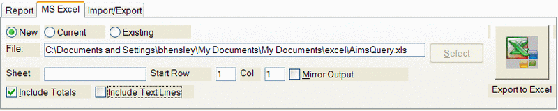
There are options to export to a New, Current or Existing excel
file. The New
option will create a new excel file and will begin populating the file
at the Starting Row and Column specified. The Current option
will export the data to the current open excel file and will begin
populating the file at the starting row and column specified. The
Existing
option will export the data to an existing excel file and will begin
populating the file at the starting row and column specified. If
exporting to a New or Existing MS Excel file, a file name needs to be
specified or selected. To specify the name of the Sheet for
exporting to within the MS Excel spreadsheet type the name of the sheet
in the sheet field. The Start Row and Col, tells the
export
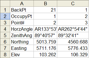
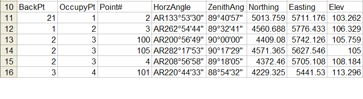
routine where to start populating the specified MS Excel file. The Mirror Outputoption
organizes the data exported in rows instead of columns. The Include
Text Lines option exports the header information and the
closure information to the MS Excel file.
 |
| Example of Mirror Output Option |
 |
| Without
Mirror Output |
Import/Export Tab: This tab provides controls to Export files and manage Reports.
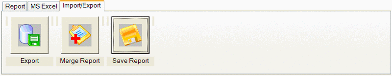
Export: This
option contains various output options for the process
report. Options to output to the following formats are available:
XML Format (xml)
Text or CSV file (txt, csv)
MS Excel database (xls)
MS Access database (mdb)
ODBC Data sources (Misc. database formats)
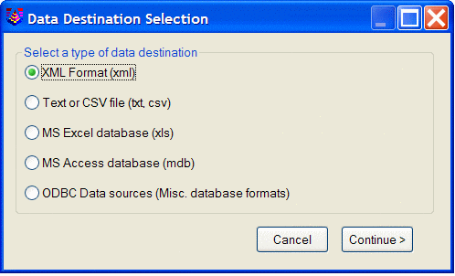
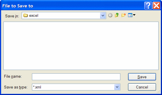
After selecting the format of the destination file select the
continue button and the file to save dialog will appear. Input
the file name to save, the type will be automatically selected based
upon the destination format.
Merge Report: This
options merges the current report with existing reports. This option is
to be used in conjunction with the Save Report
command. For example, process the file and save the report. When
processing again, select the Merge Report option and specify the
previous report file created. The resulting report will have the
current data as well as the previous data.
Save Report: This
option save the current report to the specified file.
Report
Angle Format: This option controls the
angle format displayed on the process result report. The option
of By Raw File
will display the angles in the format that is contained in the raw
file. The Bearing
option will display the angle in a bearing format. The Azimuth option
will display the azimuth of the measurement and the Angle Right
option will display the angle right measurement of the observation.
Decimal Places
for Report: This option controls the number of decimal
places for the reported data.
Report Closure: This option
determines whether the closure report will be
displayed after processing.
If processing a topo survey where the traverse has not been closed,
then turn this toggle off for
quick processing..
Report
Sideshots: Controls whether the sideshot data is shown on
the process report.
Reference
Closing Point: This is an
optional field for
entering the coordinates to compare
the ending traverse point with. This reference closing point is used to
calculate the closure.
Without using this option the program will by default use the starting
coordinate as the reference
closing point.
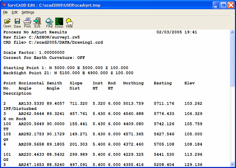
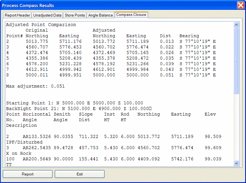
The Tabular
Report Viewer
displays a report viewer consisting of tabs. Each tab organizes and
displays different data depending upon the
process option chosen. The process results using the No Adjust
method results in three tabs the Report Header, Unadjusted Data and the
Store Points tabs. Each of these tabs display different
information which corresponds to the tab title. Using an
adjustment method results in five tabs. In addition to the three
listed above, an Angle Balance and Compass Closure tab is added. From
the Tabular Report Viewer, the Standard Report Viewer can be
switched to by pressing the Report option at the bottom of the
dialog. This is useful when wanting to combine all tabs into one
report for printing or saving to a file. An example of a Tabular
Report for a compass rule adjustment is shown below.
Processing
Methods
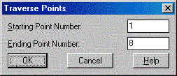
No Adjust: No Adjust means that no angle balance or traverse adjustment will be applied. Options are specified in the Process Options dialog. After picking OK for the process options dialog, a Traverse Points dialog appears for entering the starting and ending point numbers.
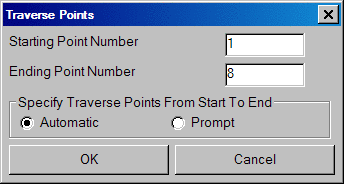
The program reads the raw file to set the defaults for these point numbers which are used to calculate the closure. The difference between the ending point and the reference closing point is the closure error and the sum of the traverse distances from the starting to the ending point is used as the total distance traversed. After picking OK for the second dialog, the program starts processing the raw file from the top record down. The result is displayed in the Standard Report Viewer which can save, print or draw the report.
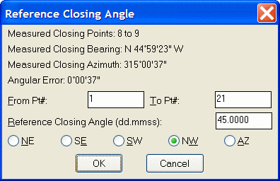
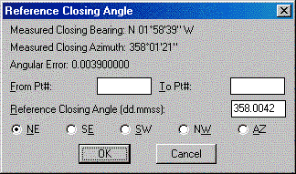
Angle Balance: This process method applies an angle balance to the traverse lines when calculating the coordinates. The angle balance takes the angular error divided by the number of traverse lines and adjusts the angle of each traverse line by this amount. The angular error is the difference between the angle balance shot and a reference angle. The angle balance shot is specified as a type AB or CL+AB record in the raw file. If no AB record is found in the raw file, then the program will prompt for which traverse shot to use as the angle balance shot. The angle from the angle balance shot is calculated as the angle from the occupied point to the foresight point. The reference angle can be specified as a bearing, azimuth or by two point numbers in the dialog shown.
The angle balance report shows the unadjusted points, the unadjusted closure, the angular error, the adjusted points and then the adjusted closure. Typically but not always, applying the angle balance correction will improve the traverse closure.
Compass, Crandall, Transit: These process methods apply the selected rule to the traverse lines when calculating the coordinates. After adjusting the traverse, the sideshots are also recalculated. The closure error is calculated as the difference between the closing shot and a reference point. The closing shot is specified as a type CL or CL+AB record in the raw file. If no CL record is found in the raw file, then the program will prompt for which traverse shot to use as the closing shot. The foresight point is used as the closing coordinate. The reference point can be specified by point number or by entering the northing, easting and elevation. The process results report shows the unadjusted points, closure error, adjustments to each traverse point and adjusted point.
Prepare Least
Squares Data: From the raw file data, this routine makes
initial calculations for
the coordinate points in the
traverse.
This data, along with the control point coordinates and the angle
and distance measurements, is
stored to a data file with the same name as the current RW5 file except
with a .LSQ extension (ie:
survey.lsq goes with survey.rw5). The constraints of the routine are:
All angle readings must be in angle right mode.
The coordinates of the starting and the ending points must be known.
The routine begins with a dialog for specifying the reference closing coordinates and any scale factors to apply to the distance measurements. The Reference Closing Point is the last point in the traverse, whose coordinates must be known. If an angle balance shot is used in the traverse, the Reference Angle Balance Angle must also be specified, either as a value or as the angle between known points.
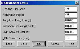
Since angles and distances have errors of different magnitudes, they are normalized using weights, based on the accuracy and confidence with which these quantities have been measured. There is a dialog for specifying the estimated measurement errors. The Reading Error is the horizontal angular error in the instrument. For example, for a "5-second" instrument this error would be 5. The Pointing Error accounts for several factors in the horizontal angle reading including accuracy lining up the crosshairs on the target, the target size and the optical quality of the instrument. The Target and Instrument Centering Errors are the distance off the point due to faulty centering. The EDM Constant Error is the accuracy of the instrument distance measurements. The EDM Scaler Error is entered in parts per million for the increased error in longer measurements. These settings can be saved and loaded as a way to store settings for different equipment.
The program will calculate the weights for each distance and angle
measurement using
these measurement errors. The control points, points to adjust,
distance and angle measurements
with weights are reported. You can edit these measurements and weights
using the Edit
Least-Squares Data routine or go directly to the Process Least-Squares
Data routine.
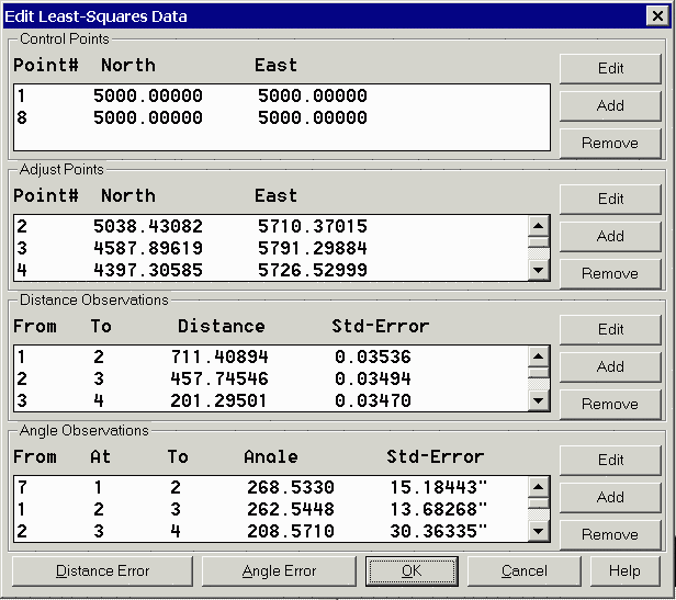
Edit Least Squares Data: This routine edits the points, measurements and weights stored in the .LSQ file associated with the current RW5 file. The editor works through the dialog shown. You can edit, add or remove the control points, adjust points, angle measurements or distance measurements. The program does not check that the editing is valid. So you need to make sure that your changes keep a good set of least-squares data (i.e. don't delete a needed control point). The Distance Error button allows you to set the distance standard error weights for all the distance measurements to the same value. Likewise the Angle Error button sets the standard error weights for all the angle measurements.
Control Points
Point# Northing Easting
1      5000.000 5000.000
8      5000.000 5000.000
Distance Observations
Occupy FSight Distance StdErr
1      2      711.409  0.018
2      3      457.745  0.017
3      4      201.295  0.017
4      5      497.024  0.018
5      6      223.972  0.017
6      7      233.872  0.017
7      8      387.073  0.017
Angle Observations
BSight Occupy FSight Angle        StdErr
7      1      2      268d53'30"    7.617"
1      2      3      262d54'48"    6.869"
2      3      4      208d57'10"   15.194"
3      4      5      247d16'57"   14.222"
4      5      6      277d48'35"   12.262"
5      6      7       92d41'13"   15.818"
6      7      8      261d27'56"   12.991"
7      1            S 01d59'18" E  0.001"
Process Least Squares Data
This routine applies a least-squares adjustment to the data stored
in the .LSQ associated with
the current raw data (.RW5) file. The closing errors are distributed
among the other points, using
the "Method of Least Squares" (Ref : Wolf, P.R. and Ghilani, C.D.,
1996, "Adjustment
Computations", John Wiley and Sons, NY,Third Edition). After the
adjustment, the rest of the raw file is processed to recalculate the
sideshots. There is an option to draw
standard error ellipses around the adjusted points. The ellipse axes
are multiplied by Ellipse Scale Factor
to make the ellipse larger for easier viewing.
The least-squares process report shows the input data and the
results. For each point, the
amount adjusted and the standard error in X and Y are reported. The
Reference Standard Deviation is
based on the sum of the residuals and the initial estimated standard
errors. The Chi-Squares test is
a goodness-of-fit test that checks the reference standard deviation
with the least-squares model.
If this test fails, there may be a blunder in the measurement data or
the initial estimated standard
errors were too low or too high.
Stadia Processing Method: Provides functionality to process Stadia surveying notes. Stadia sighting depends on two horizontal cross-hairs, known as stadia hairs, within the telescope. These hairs are parallel to the horizontal cross-hair and are equally spaced above and below it. The distance between the two stadia hairs is known as the intercept. The distance from the instrument to the rod is 100 times the intercept. For example, an intercept of 3.10 would represent a distance of 310 (3.10 X 100). For entering in stadia notes, you would enter the horizontal angle, the distance (entered as the intercept X 100) and the vertical angle.
GPS: The process GPS
routine allows for reduction of GPS records that reside in a raw
(*.RW5) file from latitude, longitude and WGS84 Ellipsoid Height to
State Plane or local coordinates. When selected,
the GPS Settings dialog will appear as shown below.
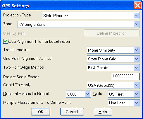
GPS>Projection Type:
Defines the datum coordinate system to be used for converting the
latitude, Longitude and WGS84 Ellipsoid height collected from the GPS
receiver into Cartesian coordinates. The supported projection
types are State Plane 83, State Plane 27, UTM, Lat/Long, Great
Britain-OSGB36, Australia, New Zealand-NZGD2000, New Zealand-NZGD49,
and France NTF-GR3DF97A. A User-Defined option is also available for
defining a user projection.
The supported geoids include: Geoid99 (USA), Geoid03 (USA), EGM96
(World), GDA94 (Australia), CGG2000, HT 2.0, HT HT 1.01 (Canada) and
)SGM02 (Britain). GeoUser-Defined
projections are supported. To define a new projection select the
Define Projection option. This will bring up the following dialog.
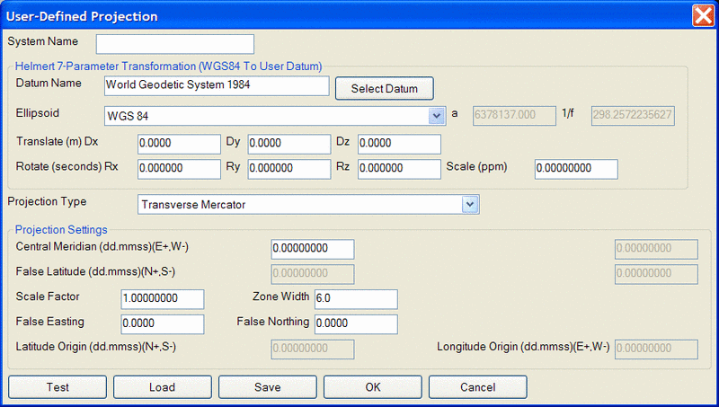
Enter a name for your system (e.g. PRVI for Puerto Rico/Virgin
Islands), then select a Projection type and enter the appropriate
parameters. Note that all latitude and longitude values are in
Degrees Minutes and Seconds (dd.mmss) and False Northing and False
Eastings are always presented in meters. Define a Datum shift by
selecting the Select Datum radial button. You may select a
predefined Ellipsoid or set your own parameters by typing in a new
ellipsoid name in the Ellipsoid field and entering values for a and
1/f. When you enter in a new Ellipsoid name, the Datum name field
will be blank. The values for Dx, Dy, Dz, Rx, Ry, and Rz and
scale are "to WGS84". If the values you have are "from WGS84",
simply reverse the sign of each value (positive becomes negative and
vice versa).
You may save your system to a "udp" file. To Load a user
defined coordinate system from a file, select the Load radial
button. A list of user defined systems will be displayed. Select the
desired system and press OK.
GPS>Zone: for State
Plane projections, you must select the correct state zone that you are
working in. For UTM, the Automatic Zone option will have the
program automatically user the program automatically use the correct
UTM zone for your location. Otherwise for UTM, you can manually
set a specific UTM zone. This manual option applies to working on
the border between zones and you want to force the program to always
use one of those zones.
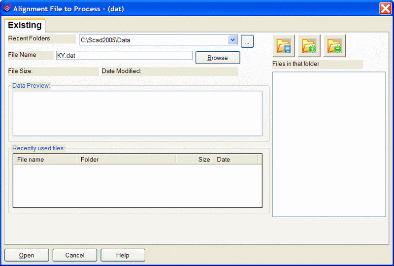
GPS>Use Alignment File For
Localization: With this option toggle on, a prompt for
the Alignment File to Process will be displayed. This file is
typically created by SurvCE (Carlson's Data Collection System) using
the Localization routine or by Carlson Field Using the Align to Local
Coordinates routine. This file (*.DAT) contains the parameters to
transform the derived State Plane coordinates to the defined local
coordinates.
At the end of the process, the coordinates will be written to the
current coordinate (*.crd) file and a report will be presented in the
Carlson editor for saving or printing purposes.
GPS>Transformation: The
transformation in the align Local Coordinates command can either be by
plane similarity or rigid body methods. The difference is that
the
rigid body method does a transformation with a translation and rotation
and without a scale The plane similarity does a rotation,
translation
and scale. This option only applies when two or more points are
used
in Align Local Coordinates or the Localization routine in SurvCE.
GPS>One Point Alignment
Azimuth: This option applies to the rotation when using
one point in Align Local Coordinates or the Localization routine in
SurvCE. For this alignment method, the state plane coordinate is
translated to the local coordinate. Then the rotation can use
either the state plane grid or the geodetic as north. No scale is
applied in this transformation. The state plane and geodetic true
north diverge slightly in the east and west edges of the state plane
zone. This option allows you to choose which north to use.
GPS>Two Point Alignment
Method: There are two option when using this method, Fit
& Rotate and Rotate Only. Fit & Rotate will use the second
point in the localization file for direction and scaling. The
Rotate Only option allows you to use the second point in the
localization file for direction but not for scaling. When using
the Rotate Only option, any scale factor entered in the Project Scale
Factor will be used.
GPS>Project Scale Factor: For
most applications, the Scale Factor should be set to 1.0. The
scale factor represents the “combined” grid/elevation factor that
reduces ground distances to grid. After
converting the LAT/LONG from the GPS records to state plane coordinates
and applying the coordinate alignment (Localization) file, the Project
Scale Factor is applied as the final adjustment to the
coordinates. This adjustment is used on the X, Y, and not the
Z. The Project Scale Factor is applied by dividing the distance
between the coordinate and a base point by the Project Scale
Factor. The coordinate is then set by starting from the base
point and moving in the direction to the coordinate for the adjusted
distance. The base point is the first point in the alignment
(Localization) file. If there are no points specified in the
alignment file, then 0,0 is used as the base point. If using an
alignment file (Localization File) this value will be automatically
calculated and displayed. Manual entry of a scale factor is also
permitted and is often used with the Two Point Alignment Method when a
scale factor is known.
GPS>Geoid to Apply: The supported geoids include: Geoid99 (USA), Geoid03 (USA), EGM96 (World), GDA94 (Australia), CGG2000, HT 2.0, HT HT 1.01 (Canada) and SGM02 (Britain).
This
option will account for the geoid undulation in determining the
orthometric elevation of the measurement. The definition of the
geoid model as currently adopted by the national Geodetic survey is the
equipotential surface of the Earth's gravity field which best fits, in
a least squares sense, global mean sea level. Orthometric
elevation measurements are used in survey calculations. In order
to convert ellipsoid heights (He) as measured by GPS into orthometric
elevations (E0), you must provide for a correction between the
GPS-measured ellipsoid (reference ellipsoid) and a constant level
gravitational surface, the geoid. This corrections is the geoid
undulation (Ug). The formula is He=Eo + Ug.
Carlson applies the Geoid model by subtracting the Geoid undulation
from the GPS elevation. The resulting elevation is then used and
displayed. In practice, the Geoid model is most applicable to two
types of alignment scenarios. One of these types is when setting
up the base over a know point and having no alignment control
points. The other is when there is one alignment control
point. When using multiple alignment control points, the Geoid
model is not as important because Carlson can model the elevation
difference which can generally pick up the local Geoid undulation.
GPS>Units: Coordinates
can be reduced into one of three available units, Metric, US Feet or
International Feet.
Process>Process Settings: This
option allows for the setting of user preferences and tolerances to be
used during processing and generation of reports.
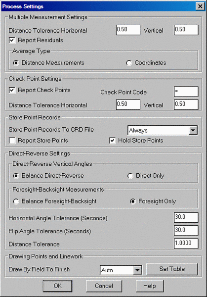
Process Settings>Multiple
Measurement Settings: These
options provide control for managing how multiple measurements to the
same point are handled and reported.
Distance
Tolerance Horizontal and Vertical: Allows for user input
of desired tolerance values for multiple measurements. Exceeded
tolerances will be displayed on the process results report. With
the Report Residuals option ON, the residual values of the measurements
will be shown on the process results report.
The data to be averaged can be either the Distance Measurements or the Coordinates.
Process Settings>Check Point
Settings: These options provide user controls for survey
check points. With Report
Check Points
ON, any point coded as a check point in the raw data file, will be
reported. When selected the Check Point Code
and Distance Tolerance fields become active and allow for
editing. The Check
Point Code is a user specified code entered in during the survey
that tells the program to check the coordinates of a particular point
with the coordinates of another point. This code is configurable
by the user. An example of a point description coded as a Check
Point would be as such, "trav =8". This description tells the
program that the description of the point is "trav" and to check the
coordinates of the this point with that of point #8. The Distance Tolerance
Horizontal and Vertical are
user specified tolerances for the check point. If either of these
tolerances is exceeded it will be reported on the process results
report.
Process Settings>Store Point
Records: These options control how any store point (PT)
record is handled during processing of the raw data file. There are
three options for storing Store Point (PT) records, Never, Always, and When CRD Empty. Never prevents
any Store Point (PT) Record Report in the raw file from being written
to the crd file. With this option on no existing point in the crd
file would be overwritten. Always will
write to the coordinate file and will overwrite any existing point with
the same number of the Store Point (PT) records. The When CRD Empty
option will only write Store Point (PT) records to the coordinate file
when it is empty. Report
Store Points
displays all store points in the process results report. The Hold Store Points
option will hold the coordinate values for the store point record when
measurements are taken to the store points. This will prevent the
coordinates of the point from changing if measurements to the point
dictate a change in coordinate position.
Process Settings>Direct-Reverse Settings:
Direct-Reverse Vertical Angles: This
option determines how to handle direct-reverse vertical angle
measurements when processing. Balance Direct-Reverse
will take the mean of the direct-reverse measurements and use this
value when processing the file. Direct Only will
only use the direct measurement to the point for processing.
Foresight-Backsight Measurements: Balance Foresight-Backsight allows for
averaging in the Foresight and backsight measurements when using
direct-reverse sets. The Foresight Only option will average the
foresight measurements only of a direct-reverse set.
Horizontal Angle Tolerance (Seconds): This
is the tolerance that the angle measured by the direct
measurements and the angle measured by the reverse measurements in a
direct-reverse set must fall within.
Flip
Angle Tolerance (Seconds): User specified value for the
acceptable difference in measured horizontal angles determined from the
direct (BD-FD) and reverse (BR-FR) observations.
Distance Tolerance: User specified
tolerance for the difference in distance measurements to the same
points. When this value is exceeded on a measurement, it will be
displayed on the process results report.
Process Settings>Drawing Point and
Linework: This
option controls the drawing of points and
linework using Field to Finish. It differs from the draw traverse
and sideshot lines under the Tools Menu of the Raw Editor by using a
field to finish code table (*.fld) to define how the points and
linework are to be drawn and layerized. There are three settings
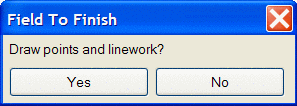
for this option, Manual, Auto and Prompt. Manual means that the
file will not be processed using the field to finish codes and no
points or linework with be drawn upon existing the raw editor. The Auto
option will use the current or last used field to finish file
(*.fld) to draw the points and lines on the drawing screen when the raw
editor is existed. The option of Prompt will give the option to
draw the points and lines to the screen. With this setting
specified, the following prompt will be displayed when existing the
editor.
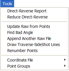
Direct-Reverse Report: This
routine creates a report of direct and reverse shots along
with
the resulting averaged
shots. Any tolerance specified in the Process
Settings>Direct-Reverse Settings section, that is exceeded will be
displayed in this report. The residuals are the difference
between the measurement and the
final average.
Reduce Direct-Reverse: This routine processes the direct and reverse shots and simplifies the raw file by replacing the sets of direct and reverse shots with the resulting average traverse record.
Update Raw from Points: This
routine is used to update the raw data based upon the
coordinates of the points contained in the coordinate (*.crd)
file. For example if the raw data has been processed using the
compass rule adjustment method, the points in the crd file are now
adjusted. However the raw data remains unchanged. If a
record of the rw5 file reflecting the angles and distances between the
points after an adjustment has been ran is desired, this routine can be
run thus updating the raw data to reflect the adjusted angles and
distances. Another application for this routine is that of
building a rw5 file for future processing and adjustment. For
example if a point file or text file has been received from another
engineering firm or fellow surveyor and you would like to build a rw5
file for future reference and processing this this option can also be
used to accomplish this. The rw5 file would be set up with the
occupied points, foresight points and the desired angle type to use
specified for the traverse. This would be all the manual entry of
the data necessary. After creating the "shell" of the traverse
then run the update raw from points routine and the raw data, as
contained in the coordinate file, will be imported into the rw5 file
thus filling out the horizontal angle, distance and vertical components
specified.
Find Bad Angle: This routine prompts for another raw data (.RW5) file which is read and the data added to the end of the existing raw data (.RW5) file. For example, if you are editing the raw file from the first days work and have a separate raw file with a second days work, you can use this routine to add the second raw data to the first raw file.
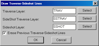
Draw
Traverse-Sideshot Lines: This routine draws lines
for all the traverse and sideshot records.
Sideshot Traverses are
traverses that do not lead to the closing or ending point. There are
different layers so that the lines can
be drawn with different colors. This command does not process the raw
file. Instead it reads the
raw file and for each traverse and sideshot record, the program looks
up the coordinates for the
occupied and foresight points in the CRD file. So it may be necessary
to run Process>No Adjust
before running this routine. With the Erase Previous
Traverse-Sideshot Lines toggled on, any previous linework drawn using
this method will be erased from the drawing screen before drawing the
lines again.
Renumber Points: This routine renumbers points in the raw file. This applies to all point numbers including: TR, SS, and PT records.
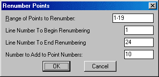
Range of Points to Renumber: Enter in the range of points to change, ie 1-4.
Line Number to Begin Renumbering: This corresponds to the line number located at the far left or the raw data editor. Enter the line number to begin the renumbering.
Line Number To End Renumbering: This also corresponds to the line number located at the far left on the raw data editor. Enter the line number to end the renumbering. If the range of numbers specified does not occur between the beginning line number and the ending line number, no changes will be made.
Numbers to Add to Point Numbers: Enter in the value to add.
This number will be added to
the existing point number to create the new point number. For example,
if
the number to add is 10
and the existing point numbers 1 and 6, the new renumber points will be
11 and 16.
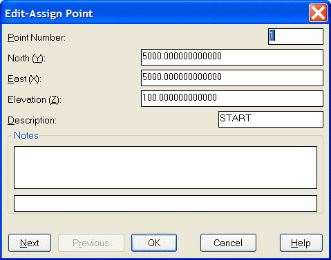
Coordinate
File: This option allows for editing and/or listing of
the coordinate data in the active coordinate file. The active
coordinate file will be displayed in the Header of the raw data
editor. Edit
Point will bring up the edit point dialog and allows editing of
the points one at a time.
The List Point
option will list the points in the active coordinate file in the
standard report viewer format. Set Coordinate Fileprovides
an option to set a new coordinate file to process to. This may be
useful when processing the raw file by different adjustment
methods for later review and comparison.
Point Groups: This option can be used to organize the survey data into point groups. There are three options for the creation of point groups, Create All Point Group, Create Traverse Point Group and Create Sideshot Point Group. The Create All Point Group option, creates a user specified group containing all of the points defined in the rw5 file. Create Traverse Point Group creates a user specified group containing only the points defined in the traverse records (TR) of the rw5 file. The Create Sideshot Point Group creates a user specified group that contains only the points defined in the sideshot records (SS) of the rw5 file.
Format of the raw data (.RW5) file
Supported record header codes with their field headers:
Traverse Examples
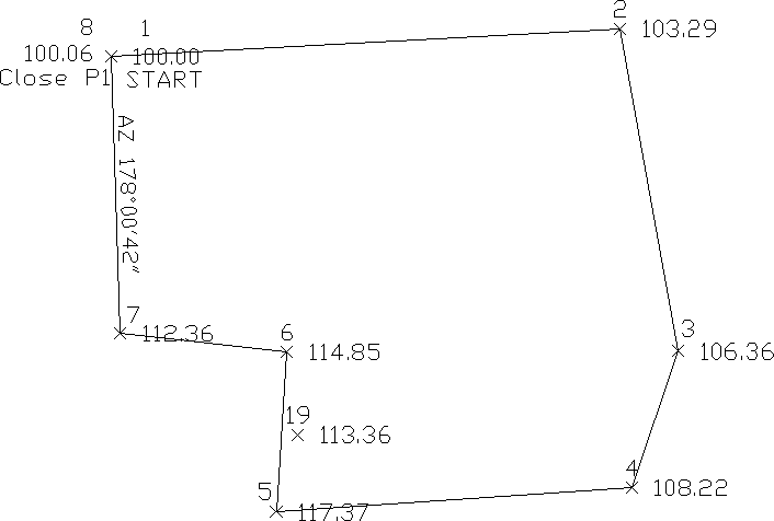 |
| This first example is a closed traverse with an internal backsight of azimuth 178d0'42" |
Use the functions under the Add menu to create and fill out the raw file as shown here.
Notice that the record from point 7 to 8 is set as a CL+AB record. This tells the program that point 8 is the closing point and that the angle from 7 to 8 is the closing angle. For traverse adjustment, the closing reference point is 1 and the closure error is the difference between point 1 and point 8. For angle balance, the reference closing angle is 358d0'42" (178d0'42" + 180). The angle balance error is the difference between this reference angle and the angle from points 7 to 8.
Now let's process using Compass adjustment with Angle Balance. Choose Compass under the Process menu and fill out the dialogs as shown.
Process Results 05/23/2002 10:06
Raw file> c:/scadxml/data/example.rw5
CRD file> C:/scadxml/DATA/example.crd
Scale Factor: 1.00000000
Correct for Earth Curvature: OFF
Starting Point 1: N 5000.00 E 5000.00 Z 100.00
BackSight Azimuth: 178°00'42"
Point Horizontal  Zenith   Slope   Inst  Rod   Northing   Easting   Elev
No.   Angle       Angle    Dist    HT    HT
Description
2     AR268.5330  89.4050  711.32  5.32  6.00  5038.43    5710.27   103.29
P2
3     AR262.5448  89.3236  457.76  5.43  6.00  4587.89    5791.20   106.36
P3
4     AR208.5710  89.1803  201.31  5.40  6.00  4397.30    5726.43   108.22
P4
5     AR247.1657  88.5235  497.12  5.40  6.00  4363.08    5230.59   117.37
P5
19    AR289.3456  91.4405  112.45  5.40  6.00  4471.32    5260.88   113.36
SS1
6     AR277.4835  90.2926  223.98  5.40  6.00  4586.54    5245.67   114.85
P6
7      AR92.4143  90.2746  233.88  5.40  6.00  4613.25    5013.33   112.36
P7
8     AR261.2756  91.4405  387.25  5.42  6.00  5000.09    4999.97   100.06
CLOSE
Closure Results (Before Angle Balance)
Starting Point 1: N 5000.00 E 5000.00 Z 100.00
Closing Reference Point 1: N 5000.00 E 5000.00 Z 100.00
Ending Point 8: N 5000.09 E 4999.97 Z 100.06
Azimuth Error : 341°38'22"
North Error   : 0.09061
East Error    : -0.03007
Vertical Error: 0.05953
Hz Dist Error : 0.09547
Sl Dist Error : 0.11251
Traverse Lines> 7
SideShots> 1
Horiz Dist Traversed: 2712.29
Slope Dist Traversed: 2712.62
Closure Precision: 1 in 28409
Remainder of process report:
Compass Closure
Adjusted Point Comparison
       Original           Adjusted
Point# Northing  Easting  Northing  Easting   Dist  Bearing
2      5038.445  5710.269 5038.440  5710.294  0.025 S 79°46'08" E
3      4587.914  5791.222 4587.907  5791.263  0.042 S 79°46'08" E
4      4397.319  5726.469 4397.310  5726.517  0.049 S 79°46'08" E
5      4363.044  5230.628 4363.032  5230.693  0.067 S 79°46'08" E
6      4586.509  5245.681 4586.496  5245.755  0.075 S 79°46'08" E
7      4613.178  5013.335 4613.163  5013.416  0.083 S 79°46'08" E
8      5000.017  4999.905 5000.000  5000.000  0.097 S 79°46'08" E
Max adjustment: 0.097
Starting Point 1: N 5000.00 E 5000.00 Z 100.00
BackSight Azimuth: 178°00'42"
Point Horizontal Zenith  Slope  Inst Rod  Northing  Easting  Elev
No.   Angle      Angle   Dist   HT   HT
Description
2     AR268.5326 89.4050 711.34 5.32 6.00 5038.44   5710.29  103.29
P2
3     AR262.5434 89.3236 457.76 5.43 6.00 4587.91   5791.26  106.36
P3
4     AR208.5704 89.1803 201.30 5.40 6.00 4397.31   5726.52  108.22
P4
5     AR247.1657 88.5235 497.09 5.40 6.00 4363.03   5230.69  117.37
P5
19    AR289.3456 91.4405 112.47 5.40 6.00 4471.28   5260.97  113.36
SS1
6     AR277.4839 90.2926 223.99 5.40 6.00 4586.50   5245.75  114.85
P6
7      AR92.4130 90.2746 233.88 5.40 6.00 4613.16   5013.42  112.36
P7
8     AR261.2758 91.4405 387.27 5.42 6.00 5000.00   5000.00  100.06
CLOSE
Shown above is the resulting process report. The angle balance had an error of 39 seconds which was divided among the 7 traverse sides. The Compass Closure shows how each traverse point was adjusted and then the resulting adjusted angles and distances.
Here is another layout of the last example that shows an external backsight setup. In this case there are two known points. Point 1 is the starting point and point 21 is the initial backsight. The setup could also use a backsight azimuth (ie north azimuth for example) instead of a backsight point number.
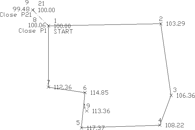
The closing record setup has changed from the last example. In this example, the shot from 7 to 8 is the closing shot with point 8 as the closing point. The closing reference point is still point 1. The angle balance shot is from 8 to 9 and the reference angle is from 1 to 21.
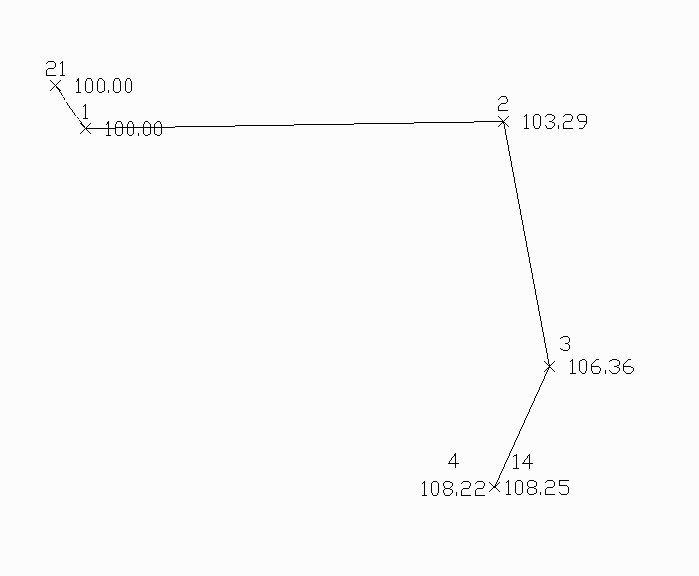 |
| Example of an open traverse |
The traverse starts from the known point 1 and ends at the known
point 14. In this case there
is no angle balance shot. The closing shot is from 3 to 4 with point 4
being the closing point.
Point 14 is the closing reference point.
The closing record setup has changed from the last example. In this example, the shot from 7 to 8 is the closing shot with point 8 as the closing point. The closing reference point is still point 1. The angle balance shot is from 8 to 9 and the reference angle is from 1 to 21.
Here is an example of an open traverse.
Compass Report from Open Traverse example:
Process Results
Raw file> d:/scdev/data/tsurvey.rw5
CRD file> d:/scdev/data/tsurvey.crd
Compass Closure
Adjusted Point Comparison
       Original         Adjusted
Point# Northing Easting Northing Easting Distance Bearing
2      5013.76  5711.18 5013.78  5711.13 0.047    N 63d21'19" W
3      4560.69  5776.42 4560.72  5776.35 0.078    N 63d21'19" W
4      4372.46  5705.08 4372.50  5705.00 0.091    N 63d21'19" W
Point Horizontal Vertical Slope  Inst Rod Northing Easting Elev
No.   Angle      Angle    Dist   HT   HT
Description

2     AR133.5324 89.4050  711.27 5.32 6.00 5013.78 5711.13 103.29
3     AR262.5506 89.3236  457.74 5.43 6.00 4560.72 5776.35 106.36
4     AR208.5712 89.1803  201.30 5.40 6.00 4372.50 5705.00 108.22
The traverse starts from the known point 1 and ends at the known point 14. In this case there is no angle balance shot. The closing shot is from 3 to 4 with point 4 being the closing point. Point 14 is the closing reference point.
Portion of typical Sokkia/SDR raw data file:
00NMSDR20 V03-05 Jan-22-98 19:14 122211
10NMW970709A
13CPSea level crn: N
02TP00015000.000005000.0000085.63500005.22000000PK-FD
08KI00035000.000005192.9200081.7450000MN-SET
07TP0001000390.00000000.00000000
09F100010003193.10000092.40416660.00000000MN-SET
09F100010100193.00000091.31388880.00000000SN-REC
Portion of typical Wild/Leica raw data file:
410001+000000SB 42....+00000000 43....+00000000 44....+00000000
45....+00000000
110002+00000002
21.124+35959590 22.104+08748240 31...1+00000000
51..0.+0012+000
110003+00000003
21.124+00000000 22.104+08748240 31...1+00267075
51..0.+0012+000
110004+00000004
21.124+00420390 22.104+08702570 31...1+00168234
51..0.+0012+000
110005+00000005
21.124+26029130 22.104+09311370 31...1+00206133
51..0.+0012+000 410006+000000IP
42....+00000000
43....+00000000 44....+00000000 45....+00000000
110007+00000006 21.124+25827090
22.104+09504550
31...1+00106228 51..0.+0012+000 110008+00000007
21.124+27151500 22.104+09312240
31...1+00106066
51..0.+0012+000
Portion of typical PC COGO raw data file:
* NEW SET UP INST. AT 1 359 59 59 ON 4
L ANG 1000 4 1 77 18 52 4.44 * 1000 WALL# 283.22
L ANG 1001 4 1 55 44 28 9.8 * 1001 WALL# 283.28
L ANG 1002 4 1 38 37 8 15.89 * 1002 WALL# 283.48
L ANG 1008 4 1 27 18 34 123.82 * 1008 WALL# 287.75
Portion of typical Nikon raw data file:
MP,NOR,,5000.0000,5000.0000,100.0000,1
CO,Temp:111F Press:29.9inHg Prism:666 23-May-2000 10:30:36
ST,NOR,,1,,5.0000,0.0000,0.0000
SS,1,5.0000,131.0605,91.3744,88.4935,10:36:15,CL1
SS,2,5.0000,137.6770,90.2923,88.5236,10:36:50,CL1
Portion of typical MDL/Laser raw data file:
D052097F04P52I494P01P02
H32473V-0639R016202P03
H06687V-0706R014936P91
H03840V-0483R017380
Portion of typical Geodimeter raw data file:
50=HAWTHORN
54=19398
23=3222
2=1
37=1000.00
38=5000.00
39=700.000
Portion of typical Survis raw data file:
_OCCUPY_PNT_
621 616 5.140
148.36076
10255015.7245 3790987.2398 87.6695 ir
10255535.8009 3790669.8100 100.3900 ir
_COMMENT_
Thu Apr 08 08:14:14 1999
_BACKSIGHT_
0.00000 90.33400 609.4200 11.900 ir
_SIDESHOT_
1 0 0
18.47550 90.55000 17.4200 5.300 TP:gps1
Portion of typical Fieldbook raw data file:
NE 32 10696.4141 10043.5613 "SN-SET"
AZ 32 27 0
STN 32
BS 27
AD 27 0.00000 NULL "SN-SET"
AD 33 183.23250 183.660 "SN-SET"
Portion of typical SurvCOGO raw data file:
19100 , 0 , 19101 , 5 , 5.25 , 4.7 , 35.15 , 550 , 91.23 ,START
19101 , 19100 , 19102 , 5 , 5.15 , 4.7 , 35.15 , 120.23 , 88.34 ,
19102 , 19101 , 19103 , 5 , 5.2 , 4.7 , 125.1444 , 180.41 , 90 ,
19103 , 19102 , 19104 , 5 , 5.2 , 4.7 , 125.15 , 240.03 , 90 ,
19104 , 19103 , 19105 , 5 , 5.3 , 4.7 , 315.15 , 305.5 , 90 ,IRON
PIN
19105 , 19104 , 19106 , 5 , 5.4 , 4.7 , 215.15 , 140.35 , 90 ,IRON
PIN
19106 , 19105 , 19107 , 5 , 5.05 , 4.7 , 215.15 , 200 , 90 ,TACK IN
FENCE
19107 , 19106 , 19108 , 5 , 5.2 , 4.7 , 300.23 , 400 , 90 ,
Pulldown Menu Location: Survey
Keyboard Command: rawedit
Prerequisite: None
File Names: \lsp\rawedit.lsp, \lsp\rawedit.arx,
\lsp\scadcfu.dcl, \lsp\scadfile.dcl