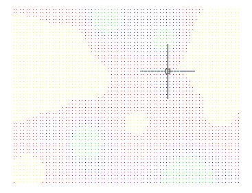
This draws the block model in the
AutoCAD drawing which can be rendered in 3D for
visualization with the 3D Viewer Window. There are two options to use
grids to limit the top surface and the bottom surface of the blocks to
be drawn. This way, if there is a new topography of the pit, it will
only draw blocks of the remaining ore. There is an option to use an
inclustion perimeter to
draw the blocks inside.
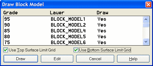
The first dialog shows the Grades, the Layer for each
grade and whether to draw them or not. The block model is drawn in
AutoCAD. It may be viewed in 3D in AutoCAD to see the various
grades,
or loaded into the 3D Viewer Window. It detects the block model and
prompts to
be rendered.
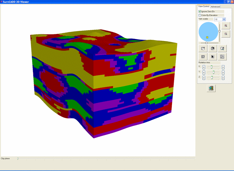
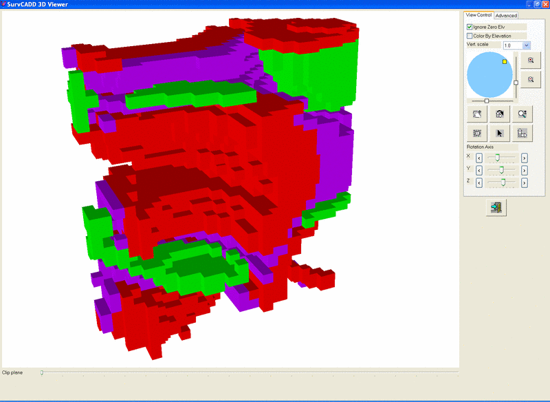
This will give a 3D rendered image of the blocks colored by grade as shown here. Using the Advanced Options of the 3D Viewer Window, colors can be turned on or off to see what is in the center, behind other grades.
Pull-down Menu Location: Ore
Prerequisite: Need a *.BLK file and a *.GPF file from Make Block Model, Input-Edit Block Model and Define Grade Parameters.