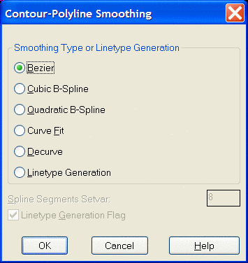
This command has options for applying smoothing to polylines. Select
the radio button for
the smoothing option you want to apply. If you use Quadratic B-Spline
type smoothing or Cubic B-Spline
type smoothing, the Spline Segments Setvar is relevant. The Curve Fit
option provides the
least smoothing, and the Cubic B-Spline option applies the most.
Another
effective way of smoothing
is by creating the contours from rectangular meshes using various grid
resolutions. Increase
the smoothing by lowering the grid resolution and decrease by raising
the grid resolution. The
Bezier option provides an incremental type of smoothing. The
Linetype Generation option turns on the Ltype Gen flag for the selected
polylines. For more information
on this option and the spline smoothing options, look up the PEDIT
command in the
AutoCAD Reference Manual. After selecting the
OK button the program prompts.
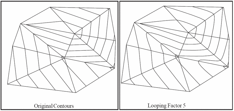
Bezier smoothing is also embedded in many of the routines that create contours. Bezier smoothing applies the Bezier smoothing algorithm to polylines. This smoothing technique has two advantages over Spline or Curve Fit smoothing. One is that a Bezier smoothed polyline will pass through all of the vertices in the original polyline, while a Spline smoothed polyline only curves towards the original vertices and can pull away from vertices at sharp corners. Hitting all the original vertices can be an important feature in contour maps for maintaining the exact location of the contours. The other benefit of Bezier is the user's ability to control the looping and vertex factors. A higher looping factor increases the curving effect. Vertices reduction can also be applied along with the smoothing. This avoids having to create smoothed polylines with numerous vertices and then having to reduce these vertices in a second step. Be sure not to make the cutoff offset for reduction too high or you can negate or even reverse the smoothing effect. A drawback to Bezier is that it cannot be decurved like the other smoothing techniques. Also, be careful with the looping factor on contour lines because a high looping factor may cause close contour lines to cross.
Enter the looping factor (1-10)
<5>: press Enter This determines the extent of
curving. 1- least curvy, 10 - most curvy.
Enter the offset cutoff <0.05>: press
Enter This value is the maximum shift distance for vertices
reduction. A
higher value removes more vertices.
Select polylines to smooth.
Select objects: pick polylines
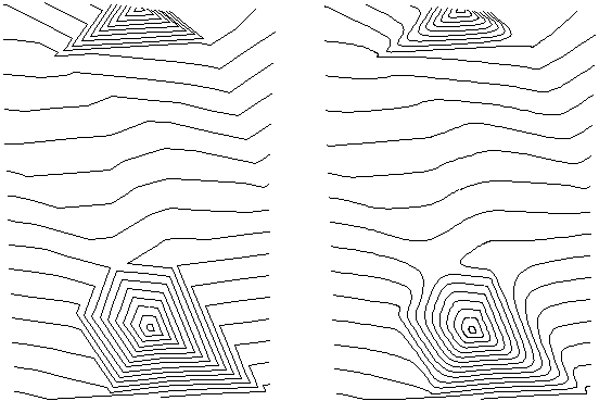 |
| Before and After |
Pulldown Menu Location: Surface > Modify Contours
Keyboard Command: Smooth
Prerequisite: Create Contour lines to smooth
File Names: \lsp\scadcntr.dcl, \lsp\scontour.lsp,
\lsp\tri4.arx