This command will stake out up to two user defined horizontal offsets to a centerline at any station, as well as an unlimited number of offsets per station, if you are using a predefined Cutsheet Station and Offset List (loaded using the Settings button). It will also stake out the centerline itself. Station intervals can be entered, and the program will auto-detect, at the user’s option, special stations such as the TS, SC, PC, PT, CS, ST and vertical curve points (including high and low points). Because individual stations and offsets can be entered, and also because pre-made station and offset lists can be recalled in the field, Offset Stakeout can be applied to virtually any offset point along a centerline.
Prerequisites and Procedures
Offset Stakeout requires both a horizontal and vertical alignment. If total stations are involved, Offset Stakeout passes through the normal backsight confirmation screens that Sideshot/Traverse and other forms of Stakeout require.
The Offset Stakeout command is a 3-screen program. The first screen identifies and loads in the alignment files. The second screen identifies the offset points to stake (slopes and distances) and the intervals or lists of stations/offsets to stake, and the final screen goes to the standard graphics, shows the target points, and guides the user to the destination, with N for Next continuing onto the next station in the interval or list.
Identifying the Alignments
The first screen has tabs for selecting both the horizontal and vertical alignments. See this next figure.
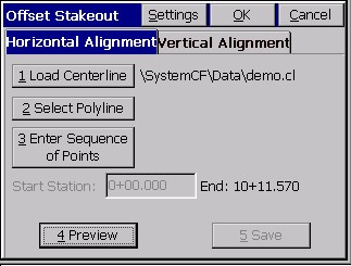
If alignments are selected from the screen, in the form of a polyline, or entered, or picked as a sequence of points, then the Start Station edit box allows you to enter the starting station. If you use a polyline or sequence of points, you can Save them (button in lower right) as a centerline (horizontal alignment) file. If a stored centerline file is used, the starting station is fixed. If you wish to ōtranslateö the starting station to a new coordinate, the centerline file may be edited in the Roading menu (eg. Input/Edit Centerline). There is no requirement that the starting and ending stations of the centerline and profile match, only that they have some station range in common to work with.
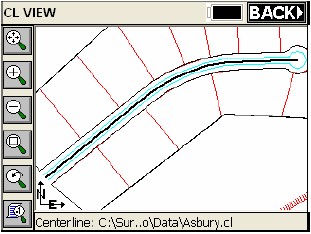
The Preview button in the Horizontal Alignment tab gives you a plan view of the selected alignment in the Map screen, as shown in this figure.
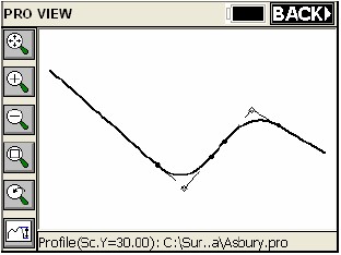
Similarly, the Preview button in the Vertical Alignment tab allows you to look at your vertical alignment in the MAP screen. The icon in the lower left corner of this MAP screen allows you to exaggerate the vertical scale as desired by increasing the value in the dialog. To return to the previous menu, simply press the ōBACKö button at the upper right of the MAP screen.
Defining the Horizontal Alignment (Centerline)
- Load Centerline: Select a centerline file defined in the Roads Menu or uploaded and converted to ō.clö format.
- Select Polyline: Select a polyline on the screen to define the alignment.
- Sequence of Points: Enter a sequence of points to define the alignment.
- Preview: Displays the alignment graphically.
- Save: If an alignment was defined by points or a polyline, you can optionally save it as a centerline file.
- Starting Station: Enter the starting station unless it was pre-determined by a centerline file.
Defining the Vertical Alignment (Profile)
This is optional in this command. If your goal is to ignore elevations and you are auto-recalling roading files, the Vertical Alignment will be used and cut/fill will appear unless you turn off ōApply Elevationsö. There are three methods of defining the vertical alignment.
- Load Profile: Select a profile file defined in the Roads Menu or uploaded and converted to ō.proö format.
- Select Polyline: Select a 3D polyline on the screen to define the profile.
- Sequence of Points: Enter a sequence of points that have elevation to define the profile.
- Preview: Displays the profile graphically.
- Save: If the profile was defined by points or a polyline, you can optionally save it as a profile file.
- Starting Station: Enter the starting station unless it was pre-determined by a profile file.
Settings
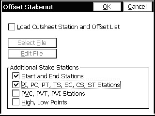
The ōSettingsö button at the top of this dialog gives the user additional options.
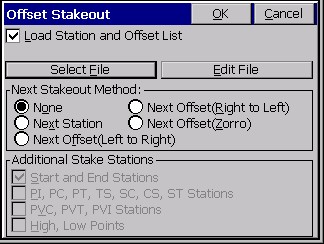
The ōLoad Cutsheet Station and Offset Listö allows the Offset Stakeout routine to use a pre-defined list of station, offset, and elevation information as defined by the user. This is sometimes referred to as ōCutsheetö list. An ASCII file with a ō*.cutö file extension is required. The file format is shown below:
Station, Offset, Elevation, Description, as in
20100, -11.5, 102.34,
20109.23, -11.5, 102.35, PC
- Select File: This allows the user to load and use a cutsheet file that has already been transferred to the collector.
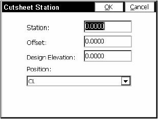
- Edit File: Displays the contents of an existing file and allows the user to remove offsets, add offsets, edit existing offsets and save changes made to the file.
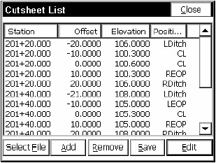
You can also create a new file by pressing ōSelect Fileö in the lower left hand corner of the Edit File dialog. Simply specify a new file name, press OK and begin adding offsets with the ōAddö button.
- Next Stakeout Method: This option controls how the Next button advances through the template or along the alignment in the stakeout dialogs.
- Additional Stake Stations: These options allow the user to direct the routine to pick up additional ōspecialö stations by toggling various options. These include PC’s (points of curvature), PT’s (points of tangency), PI’s (points of intersection, as in a sewer line) as well as spiral curve and vertical curve elements. This option is disabled when a cutsheet is being used.
Entering the Offset Points as Slopes and Distances
The Offset Stakeout screen allows you to enter one or two offsets from the centerline. The first offset is prompted in a way that expects a slope in percent and a distance. The second offset is for a curb or ditch, and is prompted in the form of ōdistance overö and ōelevation change up or downö.
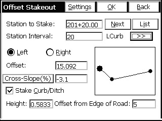
- Settings: The Settings button returns to the Settings dialog, allowing you to load another cutsheet list or specify more or less ōspecialö stations. Note that in Settings, if you called for a Station and Offset List, then most of the options in the Offset Stakeout dialog are fixed, and your only choice is to stake the particular offsets named in the list. Note also that Offset Stakeout, when not using a List, allows for the staking of 3 points on Left or Right Side: Center, Curb (or Ditch) and EOP. On the left, is becomes LEOP, LCurb or LDitch. On the right, it becomes REOP, RCurb or RDitch. You must enter data for the right as well as the left if you are staking both sides of a road. So there are 5 points total that can be staked when you use the dialog entry, since the centerline is covered in both the Left and Right scenarios.
- >>: The button in the upper right with the double arrows will switch from LCurb to LEOP to CL and back, and the large solid circle will move and highlight the correct location also.The OK button continues on to the third and final screen, for graphical stakeout.
- Back: The Back button returns to screen 1.
- Station to Stake: This is your current station to stake. When you start into Offset Stakeout, this is typically the starting station.
- Station Interval: This is the advancing station interval to stake and is specified by the user.
- Prev: This button moves to the previous station, which would typically be the station to stake minus the station interval (20120-20=20100), unless a ōspecialö station like a PC or PT is encountered, in which case it would occur as the previous station.
- Next: This button moves to the next station, which would typically be the station to stake plus the station interval (20120+20=20140), unless a ōspecialö station like a PC or PT is encountered, in which case it would occur as the next station.
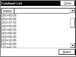
- List: This option shows the order of stations, including all special stations. If a Station and Offset List was loaded, the List option would show the stations in the list.
- Left/Right: You can specify whether to stake the left or right side of the road. The offsets are applied symmetrically. If you have a special case on the right side of the road, do the right and left separately, with separate slope and distance entries.
- Offset: This is the first offset from centerline, in the units that are configured (feet or meters).
- Cross slope: This is the first offset slope, with negative being downhill.
- Stake Curb/Ditch: This will allow user input and activate a ōsecondö slope.
- Height: This is the vertical difference from the first offset to the second offset. A positive entry is interpreted as a curb and a negative (downhill) entry is interpreted as a ditch.
- Offset from Edge of Road: This is the distance from the first offset to the second (outer) offset.
When using a Cutsheet Station and Offset list, the user must select the List button, highlight the offset to start using, and press ōSelectö. The routine will stay on this offset as it progresses through the stations until the user selects List again and specifies a new offset.
Stakeout
When OK is clicked, the program proceeds to the graphic screen for stakeout, in both GPS and total station applications. For a total station project, the prompting would appear as shown here.
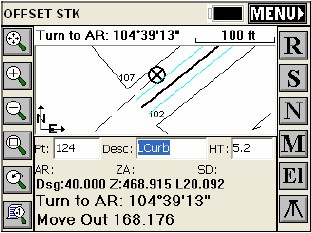
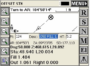
- Read (R): This button takes a reading of the current position of the target when using a total station. After taking the shot, the display will zoom in and will update the user with a new distance and direction to the target stakeout point, as shown in the next figure. This button is not present in GPS mode. In GPS or Robotic Total Station, with tracking on, your current position is read immediately. Depending on configuration in Configure Reading-Reference, the direction to stake will either be right/left distance or North/South East/West in the Map screen. The cut or fill is the elevation difference between the point read and the point being staked.
- Store (S): This will store your location to the point file. If the distance between your current position to that of the exact location of the point being staked is greater than what is specified in stakeout tolerance in ōTolerancesö, you will be prompted with ōStakeout Tolerance is Exceeded! Continue Storing?ö Selecting No will allow you to take another shot. Selecting Yes will store the point at your current position and display the Stakeout Report dialog.
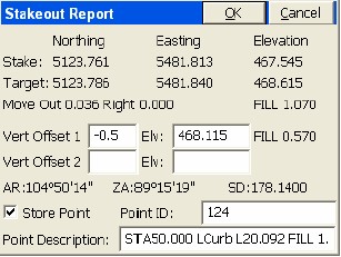
The coordinates for the Stake Point and the Target Point are displayed. The cut and fill are also displayed. The Vert Offset 1 and Vert Offset 2 allow for additional elevation calculations for the staked out point based on the input vertical offset values. If the Store Carlson Cutsheet Data in Note File has been toggled, the vertical offset(s) specified will be recorded in the .not file for the job. If using GPS, the HRMS, VRMS, and PDOP values are also displayed. Fields for Point ID and point description input are also displayed. The toggle for ōStore Pointö determines whether or not the staked out point is written to the file. After the point has been stored, you are taken back to ōscreen twoö to select the next offset point for staking.
- Next (N): This will take you to the next station for staking out the same specified offset.
- Menu (M): This takes you to ōscreen twoö where you select the station and offset to stake.
- Elevation (El): Let’s you verify the elevation that you are staking (as interpolated from the vertical alignment, if used) and let’s you override the elevation and enter a new one.
- Configure Reading (C): This takes you to the Configure Reading dialog.
- Setup: This "tripod" button, found in the lower right corner of the screen, is for total stations. It takes you to the setup screen for additional instrument setup and benchmarking.
- Monitor/Skyplot: If using GPS, this is the last button on the right side of the map screen from top to bottom. This "binocular" button opens the Monitor/Skyplot dialog. See Monitor/Skyplot in the Equip menu and section for more information on this dialog.