This command allows you to stakeout to a selected point by guiding you to the point with a series of commands and directions. There are some configuration settings that can be setup to guide you to the point with various options. You should review the Job Settings under File before staking, as there are about five settings for different methods. The dialogs are varied slightly with respect to total station or GPS equipment. Both types are documented here, illustrating the differences between the dialogs.
Note: While in Graphics mode stakeout, if you press the down arrow key, you can increase the plan view size and eliminate some of the text information. Pressing the up arrow key again reveals the cut and fill.
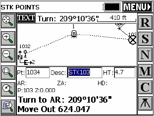
After selecting OK, the main stakeout window appears in MAP view. In manual total station mode, the angle to turn to and the distance to the stake point will be displayed at the bottom of the screen.
A read function is required to update the directional display information. You should see your points in the map with an icon of where you need to stakeout to (the circle with the X inside).
Shots are taken typically by pressing Enter. Enter also moves up automatically from the Stakeout Points “entry” screen to the Stk Points “shot” screens above. Point Stakeout can be conducted without touching the screen.
- Total Station Only: After reading and taking the shot, the display will be updated with a distance and direction to the stakeout point.
- GPS or Robotic Total Station with Tracking On: Your current position is read immediately.
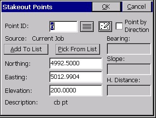
- Point ID: This is the point which you are staking. You can enter it in here and hit the enter key to view the elevation, northing and easting before selecting OK. If you want to stake out a range of points, you can enter in the points in the following format: 3-10,2,15-20. This would stake out the points from 3-10 sequentially, then point 2, then 15 through 20 sequentially. If you are using a control file in total station mode and you enter a point number which also is present in the current job file, it will choose the control file point if “control file has priority” is turned on in Job Settings, Stakeout. If you enter a point number that is not in the control file, but is in the current job’s coordinate file, then that point will be used. You can also select the points to stakeout from a list by selecting the List icon. If you select the List option, you can select the points for stakeout from the active Job file or the Control file. To do this toggle between the files by selecting between the Job and Control toggles at the top of the dialog. You can select a range of points by selecting the first point to stake then pressing the shift key and selecting the last point to stake. All points between the two selected points will be staked in sequential order. You can also add to the selection of points to be staked by pressing and holding the CTRL button and individually selecting the points to be staked. You may also select an individual point to be staked by selecting the Map icon and tapping on the point to be staked.
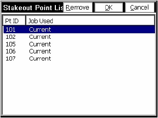
- Add to List, Pick from List: When you select or enter multiple points, they appear in the Point ID dialog “window”. You can then pick Add to List and create a list of these points, in the order selected. When you Add to List, the Point ID dialog is cleared, and you can select more points, place them in the dialog and click Add to List again. Then you can stake any of them using Pick from List, where the points appear as shown below:
- Source: When you press Enter after selecting the point or points, the program will display the source of the points, either as Current Job or Control File. The display of the source is important for verification. You may discover, for example, that someone has turned on “Control File Points have Priority for Stakeout” back in Job Settings, and this is a way to catch that.
- Northing, Easting, Elevation: You must have a northing, easting and elevation entered in for the point you are staking out. If you type in the point number of an existing point and hit OK, they will appear automatically. The description of existing points is displayed at the bottom of the dialog.
- Point by Direction: In addition to staking a point ID or entered coordinate, you can stake a point defined by a direction and distance, and even slope, from the entered point coordinate. This allows you to stake points without calculating point numbers or point IDs for the target point. Simply enter the bearing/azimuth, horizontal distance and also slope, if applicable. If the distance entry is not known but must be computer, the calculator is accessible from the distance dialog box by entering “?”.
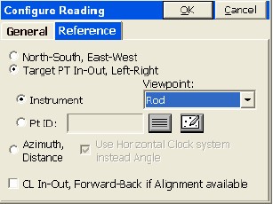
Reference
Depending on your settings in Configure Reading, Reference Tab, the direction to stake will either be right/left distance, Azimuth and Distance or North/South East/West distances. The cut or fill is the elevation difference between the point read and the point being staked. Normally, you take a shot simply by pressing Enter. After a total station shot is taken, you will see your “In-Out” distance to the target point. For total station stakeout, the direction of the reference is shown by a little arrow in the lower right of the screen.
Store Point Dialog
Selecting S to Store will display the Stakeout Report. You can turn off the “Store Point” option, and just reference the Stakeout Report screen for information. If the tolerance distance is exceeded for staking out, you will be notified and asked if you want to continue storing. (Stakeout Tolerances are set under Tolerances in the Equip Menu).
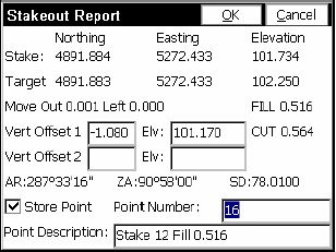
The coordinates for the Stake Point and the Target Point are displayed. The delta North, East and the elevation difference (Cut/Fill) is also displayed. The Vert Offset 1 and Vert Offset 2 allow for elevation calculations based on the input vertical offset values. If the Store Carlson Cutsheet Data in Note File has been toggled, the vertical offset(s) specified will be recorded in the .not file for the job. If under Job Settings, Stakeout, Set Cutsheet Format, a Set Pt Cutsheet Format has been established with a named file for storage, then cut and fill data will be saved to a cutsheet ASCII file. If using GPS, the HRMS, VRMS, and PDOP values are also displayed. Fields for Point number and point description input are also displayed. Pressing OK (which optionally will Store Point if clicked on) will return to the Stakeout Points dialog to select the next point for staking. If the Use Control File option is set under the Job Settings, you have the option of staking control file points. If you enter in a point number to store that is the same as a point number in the control file, the point in the control file will remain unchanged. It will only modify the point in the current coordinate file. In GPS mode, if the point being stored is the same as one in the current job file, the Point Protect dialog box appears stating that the point you chose is already used. The next available point number is listed with the option to overwrite the current point, or use the new number.
Features of TEXT Stakeout Mode
Selecting the TEXT button at the top left of the Map View screen will take you to a detailed text orientated stakeout dialog. See TEXT shown at the top left of this figure.
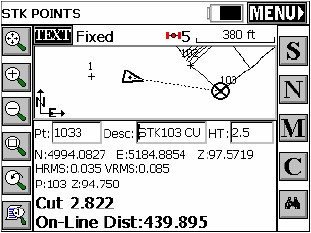
This dialog that appears has a graphical display, with a bullseye representation of the stakeout point. The type of survey equipment used -- Total Station, Robotic Total Station or GPS -- will determine the format of the graphic display and various options on the screen.
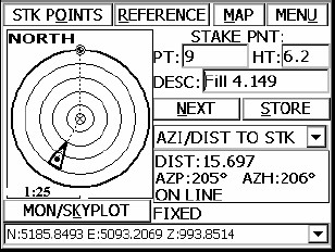
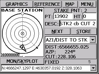
A typical GPS screen shown is shown in this figure.
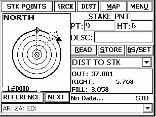
A typical Robotic Total Station screen is shown is shown in this figure.
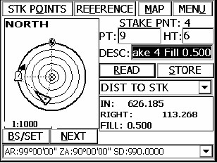
A typical Standard Total Station screen is shown in this figure below.
- Tabs: The tabs across the top of the view screen change depending upon the survey equipment selected.
- Bullseye (Graphic Display) An arrow indicates your current position in GPS and an instrument symbol represents your position using manual or Robotics. The center of the bullseye is the point to be staked. A small circle with an hour glass in it indicates your reference point. Your position is updated continuously if using GPS or Robotic Total Stations in tracking mode. If using a Manual Total Station the current position is updated after you take a reading to the position of the target. The triangle marker indicates your position in relation to the desired stake point. If you are short of the point, then the marker will be between the center of the bullseye and the instrument symbol, if using manual or robotic total stations. If the triangle is beyond the center mark you are beyond the desired stake point. As you get closer to the target, the scale of the display, located below the bullseye, is updated. When you get within your defined stakeout tolerance, each corner of the bullseye will display a diamond. Your specified reference is displayed in the upper left corner of the bullseye. For example, if your reference is North, then North will be listed at the top left of the bullseye. The survey equipment used will dictate the options located at the bottom of the bullseye. In GPS mode, the MON/SKYPLOT option, is available. In Robotic Total Station mode the REFERENCE and NEXT options are available. In Manual Total Station mode, the BS/SET (Setup) and NEXT options are available.
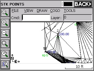
- STK POINTS or GRAPHICS: Once in the View screen, pressing the upper left tab takes you back to the map screen. If you exit the program while in the View screen for stakeout, the next time you go to stakeout the View screen will be active and is now set as the default stakeout screen. To change back to the Map screen as the default, press the STK POINTS or GRAPHIS button.
- REFERENCE: This option allows for defining a reference point for orientation of the bullseye.
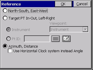
It is similar to the Reference Tab of Configure Reading. The type of survey equipment used determines reference options. With manual and robotic total stations, the reference options are North, Target Point, Instrument or Entered Point and Azimuth/Distance. With GPS, the options are North, Target Point, Base Station or Entered Point, Azimuth/Distance and Direction/Distance. North is always represented by the small circle with the hour glass, and the specified reference point is always represented by the larger empty circle. When north is referenced, the smaller circle is inside of the larger circle.
Note: Staking out in GPS by reference to a point, or to the base, is only available in the “Text” screen within the Stakeout commands. In the graphics screen, the visual display of movement towards the target point is provided, rendering these other referencing options less critical.
- MAP: This tab takes you to the map screen. When in the map screen, the BACK tab will take you back to the View screen.
- Directional Commands: These options are located below the READ and STORE buttons. These options are dependent upon the survey equipment used. The different options are: (TURN/MOVE to STK), (N/S, E/W to STK), (AZI/DIST to STK), (I/O, L/R to STK) – Manual/Robotic Total Stations. (AZI/DIST to STK), (N/S, E/W to STK), (DIST to STK), (I/O, L/R to STK) – GPS Systems. You can change the format of the directional commands at any time by selecting the down arrow and picking the format desired. TURN/MOVE to STK will always show the initial angle and distance to turn from the setup point to the stake point if using total stations. It does not update. When READ is pressed, then the directional display updates to show DIST to STK. Going back to TURN/MOVE to STK will display the original angle to turn and distance to travel.
- Directional Display: This is the data field directly under the directional commands. The information shown in this display is dependent upon the settings specified for the directional commands documented above. Survey equipment used will determine if this screen is updated continuously or requires a READ command to update. This screen displays the directional information that leads to the stake point.