SurvCE can have one pre-defined FCL (Feature Code List) file loaded with the job coordinate CRD file.
The Feature Code List file stores pre-defined field codes that define Line/Layer drawing properties and optionally GIS prompting. (More than one FCL file can exist but only one can be loaded at a time per job coordinate CRD file.)
The operator builds this FCL file using option 5 “Feature Code List” in the File main menu. See the figure below.

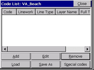
After you select 5 Feature Code List, the following Code List pop-up box is displayed. See the figure below.
FCL (Feature Code List) files can be created, edited or reviewed on a PC using Carlson X-Port or any Carlson surveying office software. (SurvCE’s FCL file is equivalent to Carlson’s Field-to-Finish FLD Table used in their PC office software. Transfer all PC Field-to-finish FLD table files using SurvCOM or Carlson Export. Select the Field Code Table option to upload the FLD file to SurvCE as a FLC file.)
Defining Field Code Line/Layer Properties
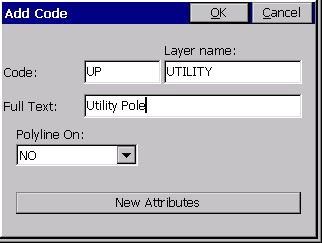
To define codes with line/layer drawn features and, optionally, GIS prompting, select in the Code List pop-up box “Add” (as shown in the previous figure). The following Add Code pop-up box allows the operator to define Field Code Line/Layer drawing properties.
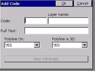
- Code: Input one word Field Code
- Layer Name: Defines the layer the linework 2D & 3D will draw in using SideShot/Traverse or Store Point
- Full Text: User defined full text description for code
- Polyline On: Yes or No defines to draw or not to draw between similar codes e.g. EP, EP1
- Polyline is 3D: Yes or No-Yes draws in 3D, No in 2D
- New Attributes: This highlights after inputting all the Line/Layer drawing properties
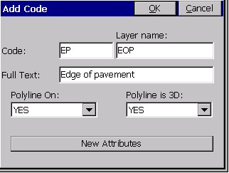
The following EP code has been input in the FCL file. When surveying using SideShot/Traverse or Store Point in the SURV menu, input field codes EP, EP1, EP2 and so on will draw 3D Polylines between these similar codes in the EOP layer. A 3D Polyline will be drawn in real-time when collecting data and inputting EP or EP# codes in surveyed points descriptions.
As mentioned above, “New Attributes” becomes highlighted after inputting all the Line/Layer drawing properties. GIS prompting information can be added for this field code. If no GIS prompting is applicable for this field code, simply pick OK and create another field code, or exit and store the FCL file.
Defining Field Code GIS Prompting
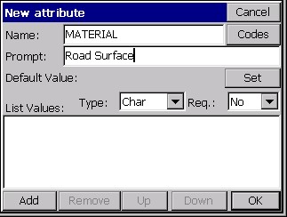
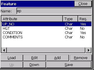
To add GIS prompting to a defined Line/Layer code, select “New Attributes”. This button can be seen in the above figure at the bottom of the dialog. The following GIS Feature pop-up box is displayed. See the next figure below. To define GIS prompting for the EP field code, select “Add” in the Feature dialog shown below. The next pop-up box that appears, titled New attribute, is then displayed (shown below, underneath the Feature dialog). The New attribute dialog creates GIS prompting.
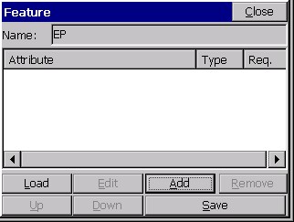
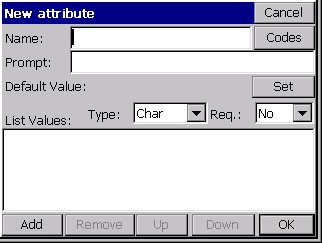
Load will load any existing Field Code GIS prompting for reuse. Edit reviews or revises existing GIS prompting. Add creates individual GIS prompting, as shown in the figure immediately above (New attribute dialog). Remove deletes any highlighted GIS attribute. Up and Down reorders the sequence of GIS attribute prompting. Save stores input or edited GIS prompting and exits to Line/Layer drawing properties.
Defining GIS Prompting
- Feature Code Name: No spaces GIS title for database
- Codes: Special codes, e.g. Date, Time, Lat, Long.
- GIS Prompt: Including spaces full name for GIS
- Default Value: Most common GIS value/default value
- Set: Lets the operator highlight and select the default value if there is a List of attribute Values.
- Type: Offers 4 options CHAR, INT, REAL and Code. Code Type will default to character type corresponding to special Codes. Codes can be Char, Int. or Real automatically.
- Req: Requisite/required entry. Operator cannot leave any GIS prompt empty when this field is set to Yes.
To add GIS attribute prompting for List Values, select the “Add” button within the New attribute dialog, as shown immediately below. The figure below that shows the New value pop-up box. The operator inputs, after selecting Add again, for each possible material (e.g. macadam, concrete, brick, stone cobbles and so on).

The data input for all GIS List Values is shown below in following figure below. Note that Macadam is highlighted and will be the default value. If there are more than six attribute List Values, scroll bars will appear. This defines only one GIS entry Material for the EP field code. Each GIS prompt for the field code EP (e.g. Material, Location, Condition, Width, Slope and so on) will require being created using Add in the Feature pop-up box, as shown earlier in this tutorial.
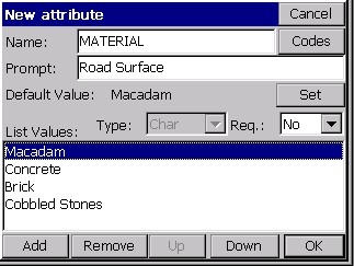
Add, Remove, Up and Down pertain to GIS List Values prompting. Add and Remove create or delete List Values entries. Up or Down reorders the highlighted List Value up or down. OK exits the GIS prompting screen retaining the GIS prompting entries and Cancel exits and discards all new inputs. The completed GIS field code for EP is shown below in the Feature dialog.
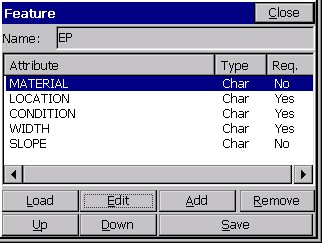
With all of the GIS Features input – Material, Location, Condition, Width and Slope – the operator can now select Save to store the GIS prompting for the field code EP. When storing points in the SURV menu in SideShot/Traverse or Store Points with EP or EP#, 3D linework when ended will prompt for EP GIS data as defined here. If 2D or 3D linework is created the GIS data will be attached to the linework. Note that Location, Condition and Width are required input GIS fields. Load allows selecting any existing field codes GIS prompting for reuse. Edit reviews or revises existing GIS prompting. Remove deletes highlighted GIS attribute prompting. The Up and down buttons will reorder GIS attribute prompting. Save stores and exits.
Importing & Exporting GIS Information from SurvCE
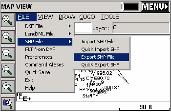
SurvCE imports and exports ESRI SHP files. SurvCE solely uses ESRI SHP files to interface with all GIS programs. ESRI SHP files are open architecture and are a widely used and accepted GIS format for most common GIS packages. To import or export GIS data to or from SurvCE, select in MAP – File – SHP File – Import or Export SHP File (Quick Import or Export only reads and writes the drawing entities and doesn’t include the GIS info). There are two figures later in this tutorial that depict this.
SurvCE Creates Three ESRI GIS Drawing Objects: Points, Arcs (Polylines) and Polygons (Closed Polylines)
There are only three types of drawing entries in ESRI SHP files points, arcs (open 2D or 3D Polylines) and polygons (closed 2D or 3D Polylines). The EP field code creates points and arcs and/or polygons. GIS information is stored only to the arcs or polygons and not the EP points. All GIS information for EP will be attached to the 3D Polylines. The second Field Code UP in the FCL job file creates points only with no linework. The UP field code attachs GIS information to the UP points. See the next two figures below.
Save Feature Code List File
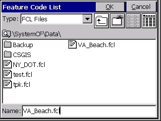
With two field codes (EP and UP) with GIS information input and stored, using option 5 “Feature Code List” (in the File main menu), lets collect some survey data in SideShot/Traverse with GIS information. First, Save As these two codes into a Feature Code List file, as shown below.
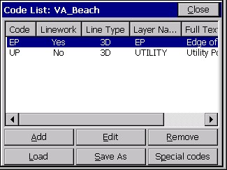
The Add and Edit buttons create or revise Line/Layer drawing properties and GIS prompting. Remove deletes field codes highlighted. Load unloads the current FCL file and loads another existing FCL Field Code List.
Collecting & Storing GIS information in SurvCE
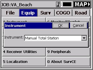
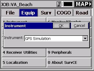
To demonstrate collecting survey data with GIS information, SurvCE is set to either Manual Total Station or GPS Simulation.
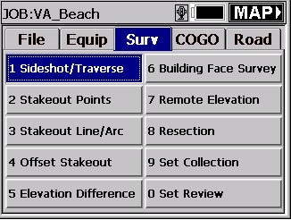
For Manual Total Station, go to the menu SURV – SideShot/Traverse (see the next two figures). Follow the figures for Manual Total Station. It is important, in the main menu, that File – Configure Reading – HGT/Desc Prompt on Save is toggled ON!
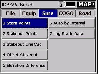
For GPS Simulation, go to the menu SURV – Store Point (see the next two figures) and follow figures for GPS Simulation.
See these Manual Total Station example screen captures, shown here in the next four figures.
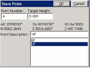
GPS Simulation screen capture examples are shown in these next four figures.
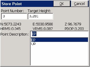
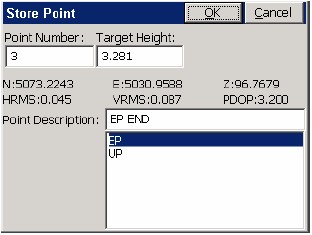
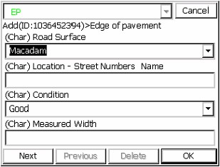
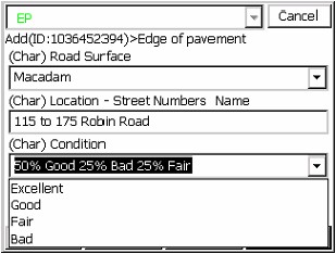
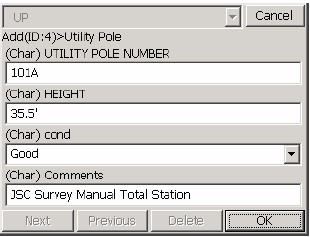
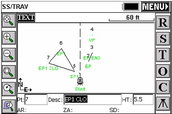
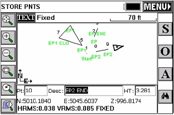
The sequence of shoots started with GPS Simulation storing points 2 and 3 as EP codes. Point 3 was stored as EP END. A 3D Polyline was drawn between 2 to 3 and GIS prompting popped-up after point 3 was stored shown above. Note in the Condition field the operator input data not found in the default settings. Point 4 was stored using manual total station as a UP point code. Point 4’s UP GIS prompting appeared after point 4 was stored. Points 5 through 7 were stored as a closed polygon. This was done by storing point 7 as EP1 CLO to close back to the start point 5 of the EP1 3D Polyline. The GIS prompting appeared for EP1 (not shown) and entered. The last sequence above was to exit SideShot/Traverse and select MAP.
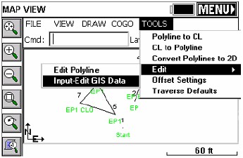
Editing GIS Information on Arcs and Polygons – Input-Edit GIS Data
To edit existing GIS information stored on Arcs (2D/3D Polylines) or Polygons (closed 2D/3D Polylines) in the MAP pop-up box, select Tools – Edit – Input/Edit GIS Data, and pick any polyline or polygon. There are two figures below. The top figure shows how the closed 3D Polyline between points 5, 6 and 7 was selected using this command. GIS data for the closed 3D Polygon is shown in the second figure.
The above figure displays the next EP code EP2 stored using GPS Simulation. When ended with a END or CLO description after EP2 SurvCE will prompt for EP GIS data to attach to the polyline as defined above.
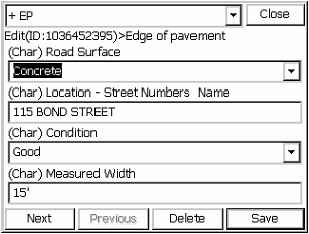
The figure above displays the ease of reviewing, creating or editing GIS data using Input-Edit GIS Data. From the MAP screen Input-Edit GIS Data was selected and the closed 3D Polyline picked on the screen. The GIS data stored prior was displayed for review or editing. Any data point, polyline or closed polyline could be selected using the Input-Edit GIS Data command in MAP and new GIS attached to this entity or existing GIS data reviewed and edited.
Editing GIS Information on Points using List Points
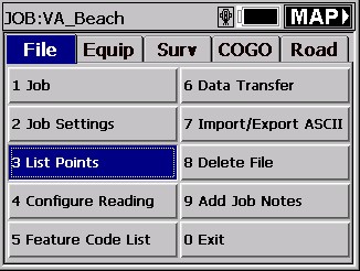
Input-Edit GIS Data only works creating, reviewing or editing GIS information on Arcs or Polygons. To create, review or edit GIS information on points use List Points shown below under File – 3 List Points.
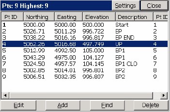
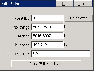
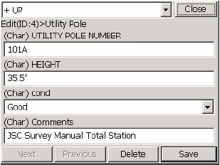
Highlight point 4 and select Edit (see figure immediately above). Point 4 is the only surveyed number with GIS data stored to the point. The Edit Point pop-up box appears, and can be seen in the next figure below. To create, review or edit GIS information select Input/Edit Attributes (See Figure 9-32).
Note: At the +UP box on top the down arrow can be selected and one or more GIS field codes could attach GIS data to this same point. Points, Arcs or Polygons can all have one or more GIS field codes attached to these entities.
Exporting SurvCE GIS Data as ESRI SHP files
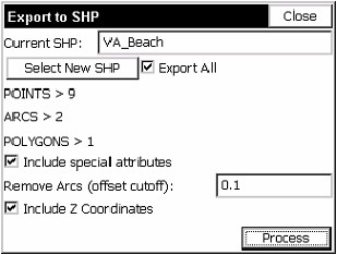
These final two figures, above, display the exporting of our VA_Beach MAP and GIS data. The ESRI SHP file consists of 9 points, 2 arcs and 1 polygon (closed polyline). Only one point, point 4, has UP GIS data. Two arc polylines and one polygon have EP GIS information attached. Note that Include special attributes is checked. This adds to polyline arcs and closed polygons the polylines length and area to the GIS data automatically. Process with Export All checked stores the VA-Beach three SHP files automatically to a user defined subdirectory and a fourth SHP file with 8 points without GIS data.