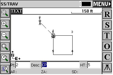
In the example below, as shown in the next figure, the traverse was performed by occupying point 1 located at the NW corner of the block. The initial backsight was established by azimuth, measured and stored as point 2 shown NW along the hanging leg. Angles and distances were measured in a clockwise direction. Point numbers 6 and 1 are at the same location and point numbers 7 and 2 are at the same location. This method allowed for the closing of the angles and the measurement of all traverse legs.
Process Raw File
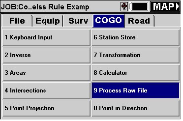
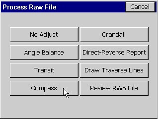
Select “Process Raw File” from the “COGO” tab, as shown below in this figure.
Select Raw File
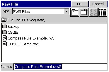
The next figure below shows the standard Windows file selection dialog. Select the RW5 file you want to process followed by the “OK” button.
Select “Compass” from the adjustment options dialog box as shown in this figure below.
Reference Closing Point
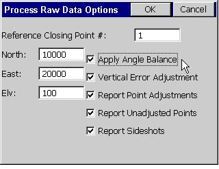
Key in the initial occupied point number for the “Reference Closing Point #:” and toggle on the “Apply Angle Balance” option, followed by the “OK” button, as shown in the next figure below.
Closed Traverse
In a closed traverse scenario, the reference closing point will always be your initial occupied point name.
Note that you will need two known points, or one point and a known azimuth, for a closed traverse. The angle balance point will be the same location as the original backsight and will not be adjusted.
Open Traverse
In an open traverse scenario, the reference closing point will be a stored point name or coordinates that represents the known values for the last occupied point in the traverse.
Note that you will need two known points, or one point and a known azimuth, at the beginning and at the end of an open traverse; one point at the end will be used to close on and other will be used for angle balance (When Angle Balance is applied). The angle balance point will be the same as the last foresight point in the traverse and will not be adjusted.
Traverse Points
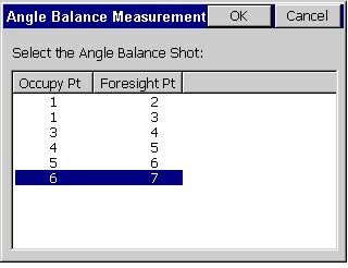
You’ll notice in the Angle Balance Measurement figure below, since you keyed in the data yourself, that the number of traverse points in this survey is 7. Since point 7 was only measured to avoid and record the closing angle balance measurement by hand, in this example the traverse is only from points 1 through 6. Replace the 7 in the “Ending Point Number” input box with a 6, as shown in this next figure immediately below, followed by the “OK” button.
Note that point 6 should be the same location as point number 1 in a closed traverse.

Angle Balance
Select the foresight shot from the last occupied point to the original backsight location. In this example we would select the leg measured from point 6 to point 7, since point 7 was our foresight angle balance shot to point 2. Press the “OK” button. In an open traverse, this would be the measured leg that represents the known azimuth or bearing at the end of the traverse.
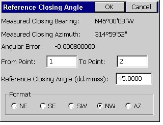
Reference Closing Angle
Finally we need to provide the reference closing angle (record). This is the original backsight azimuth. Key in point 1 and point 2, or key in the known azimuth or bearing, followed by the “OK” button.
In an open traverse, key in the stored point numbers that represent the values for the known control points at the end of the traverse, or key in the known azimuth or bearing.
The adjustment report should be presented, and the adjustment should be complete. The angle balance point number 7 will not be adjusted to fit point number 2, and can be discarded.