|
Input-Edit Centerline
|
|
Input-Edit Centerline
|
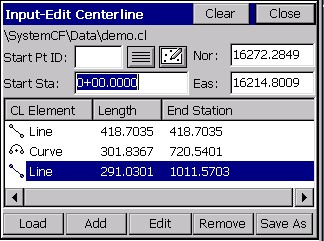
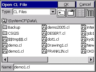
This command allows you to enter new centerlines, as well as recall and edit existing centerline files. Centerline files in SurvCE are ASCII files with a .CL extension. When the routine is selected, you are immediately placed in a dialog, where you can Load existing centerlines or begin entry of new centerline information.
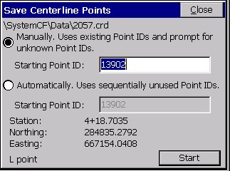
Note: You can create new points with Input-Edit Centerline. When you enter and save a centerline, it will prompt “Do you want to save centerline points?” You may answer Yes and save point ID’s for the start, end, PI, PC, radius point, PT and any key spiral points found in the file. In the same way, a centerline that you load can be re-saved with new coordinate ID’s assigned to all key points, as long as you make some change, like adding a point number to one of the Pt ID fields for a CL Element. If you answer Yes to Save Centerline Points, the dialog box below appears. If you have entered point ID’s of your own choosing in the Input-Edit dialogs, use the upper option. The lower option will auto-number from the starting point ID without regard to any numbers you’ve entered, but will respect and not overwrite used points in the file.
Points are not stored to the centerline file itself, so after loading a stored centerline, no point ID’s will appear.
Line: A tangent section of the alignment.
Curve: A typical circular curve section of the alignment.
Spiral-Curve-Spiral: The Spiral-Curve-Spiral element is really just 2 implementations of Spiral Only (line-spiral-curve and curve-spiral-line). The advantage of Spiral-Curve-Spiral is that it completes 3 elements at once and is a fairly common application on high-speed highways.
Spiral Only: The Spiral Only element will handle a spiral between any line and arc segment (eg. line-spiral-arc or arc-spiral-arc).
A Simple Sewer Line Example, by Point Number
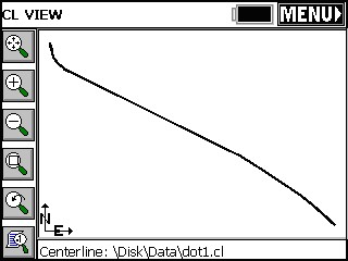
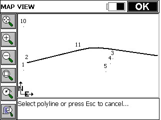
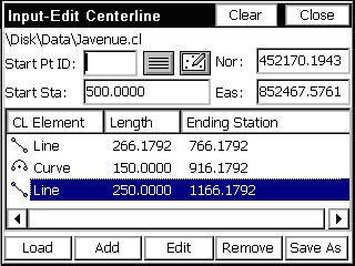
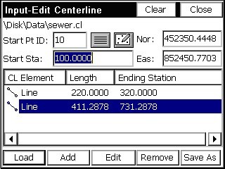
Centerlines can be very complex or very simple. Perhaps the simplest form is a point-to-point sewer line, without any curves or spiral curves. Such a centerline, if it exists on the map screen, could be picked using the Pick PL option. But if you only have point numbers, you can enter them. Referring to MAP View figure above, we could create a centerline representing manholes at points 10, 1 and 5. Begin by entering point 10 as the Start Pt ID in the Input-Edit Centerline dialog. Enter a Start Station of 100. Then select Add and choose Line (the default option, so you can press Enter). You will see the “Line” dialog. Fill out the End Pt: (next point) as point 1.
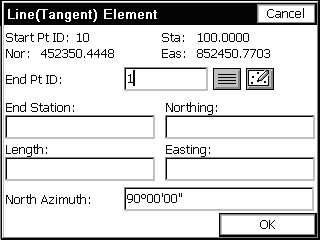
When you press Enter to accept 1, it recalls the coordinate of 1, computes the length of the line element and then also computes the bearing of the line element (see next figure). Note that if you don’t have point numbers for a line segment, you can enter the Bearing and Length (or Bearing and End Station) to define the starting line segment.
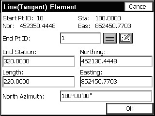
When the first segment is entered, you can click OK, or enter your way through the dialog items and back to the main menu. See the figure below.
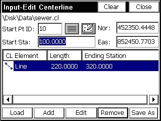
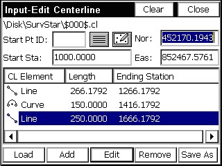
The procedure is then repeated for point 5, the second and last line segment. The fastest approach is to select Add, press Enter (for Line), enter the point number, tap OK and repeat. It is a total of three keystrokes, not counting entry of the point number. The final screen is shown below.
A Highway Centerline Example, From Plans
Highway Centerlines are the most complex form of centerline, because they can include curves and spiral curves. Though centerlines and profiles can be entered using office software and downloaded to SurvCE as LandXML files or as native files in SDR33 format and converted to SurvCE format, it is often necessary to enter these files in the field. Sometimes this entry process is based on a concise printout of centerline and profile information, and sometimes it must be read from actual paper plans of the road project. We will examine the procedure for centerline entry direct from paper plans (e.g., what to look for, what to enter). The first thing to look for is the starting station. See this figure below.
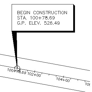
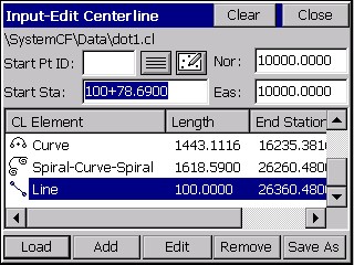
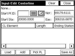
The starting station is 100+78.69. We can now proceed to Input-Edit Centerline, found as menu item 1 in the Road menu of SurvCE. With this item selected, the first dialog appears and is filled out as shown in this figure.
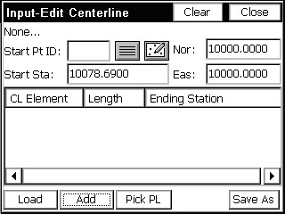
If the starting coordinates are known, these should be entered. It should be noted that all coordinates in a centerline will automatically translate if the starting coordinates are later revised.
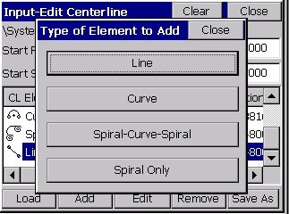
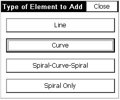
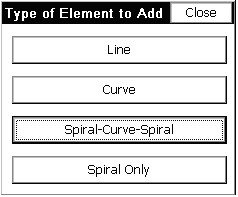
Once the starting coordinates are entered, you select Add to add each element of the centerline. Supported elements include lines/tangents, simple curves, spiral-curve-spiral and spiral only, as shown in this figure.
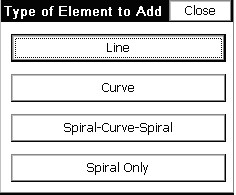
Note: The Spiral Only element will handle a spiral between any line and arc segment (eg. line-spiral-arc or arc-spiral-arc). For that reason, the Spiral-Curve-Spiral element is really just 2 implementations of Spiral Only (line-spiral-curve and curve-spiral-line). The advantage of Spiral-Curve-Spiral is that it completes 3 elements at once and is a fairly common application on high-speed highways.
The first element or segment of the centerline is a tangent section up to the first PC. The paper plans show the station of the first PC and the bearing into the first PC (see the next figure), which will be entered next within the Line Element dialog.
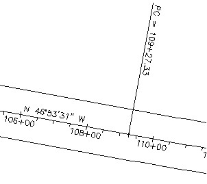
The PC of the simple curve is 109+27.33. This is also the end of the tangent section (or the line element). The bearing into the PC can be read as N 46°53’31” W. After you select Line, fill out the dialog as shown in this next figure.
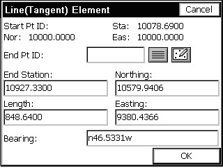
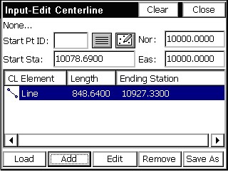
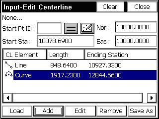
Note that all other tangent sections, assuming they are tangent to the previous curve or spiral elements, can be entered simply by filling out the end station dialog box (one entry). On the very first tangent section, the bearing must be entered. When Enter is pressed after entering the bearing as n46.5331w (or nw46.5331), it converts to a degree, minutes and seconds presentation. If configured grads/gons, 46.5331 remains in decimal form. When Enter is presses after typing in the End Station, the program calculates the Northing, Easting of the End Pt. and the Length of the tangent section. If the length was known (and the PC station was not known), then length could be entered, and that would calculate the End Station of the tangent. Click OK to move onto the next element. Returning now to the Input-Edit Centerline dialog, we now have an element entered, as shown in this figure.
Now you select Add for the next element, which is a Curve (simple curve). Select the Curve option, as shown in this figure below.
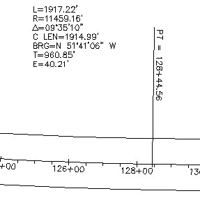
This opens the Curve Element dialog. Simple curves can be defined several ways, but the easiest is to enter the direction (left or right), the arc length and the radius length (three items total). All the other curve elements are then calculated. Referring to the curve data in the upper right of Figure 6-21, the arc length (or L) is 1917.23 and the radius is 11459.16. It is a curve to the left, so we choose Left in the Curve Element dialog as shown in Figure 6-24. Pressing Enter, after the entry of the second element (arc length if radius was entered first, or radius length is arc length was entered first), calculates all items as shown in this figure below.

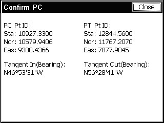
In terms of keystrokes, you can fill out the Arc Length immediately, because the cursor defaults to that position when the dialog is entered. Then Enter through the Delta angle to the Radius dialog box, and fill that out. If you do not know the radius but do know the dregree of curve, enter ? in the Rad dialog box, go to the Curve Calculator, enter the arc length and degree of curve. It will calculate the radius. Highlight and select the radius, then Copy and then Paste (top of the dialog). If you press Confirm PC/PT you can verify the Tangent Out bearing, as shown in this figure shown here.
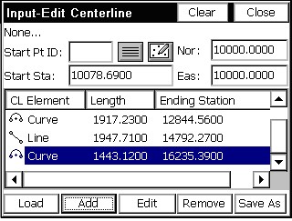
Pressing OK reveals that we now have two elements, a line and a curve (see the next figure). Press Add to enter the second line or tangent section leading up to our second curve.
On the plans, we can check ourselves by looking for the Point of Tangency (PT) and verifying the stationing. That checks, as shown below in this next figure (12844.56). Next, we click Add and select a Line segment.
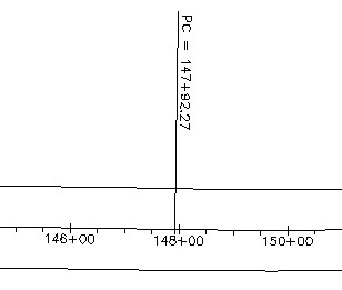
Now, we look for the next PC station, which equals the end of the next tangent. Tangent sections can also end at TS (tangent to spiral) stations as well. This next figure reveals that the next PC is at station 147+92.27.
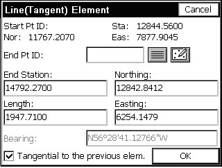
Entry for this tangent segment is one line, the end (or PC) station. Pressing Enter leads to the calculation of northing and easting and length, as shown in the next figure. Note that because the program defaults to tangential line segments coming off curves and spiral curves, the Bearing quadrant is grayed out and fixed. If the tangent segment is non-tangential, then you must check on the Non-Tangential toggle in the Line (Tangent) Element dialog.
Press OK to complete the entry for this line element. Next, click Add (or press Enter for Add) to enter the next simple curve. The curve data for this curve appears in plan view below.
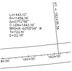
The key entry items, again, are curve direction (left), the arc length (1443.12) and the radius length (11459.16). These are entered as shown in this next figure.

Pressing OK leads to still another element added to the centerline. See the figure.
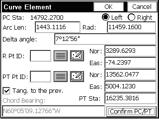
Notice that in the Curve Element dialog immediately above, the PT Station is 162+35.38. Yet we are calculating 162+35.39. This is because we entered the given arc length of 1443.12 from the PC at 14792.27. That adds up! But when you start to vary from the plans, you need to make a decision. Maybe the delta angle of 7 degrees, 12 minutes and 56 seconds (7.1256) is what governs the length of the curve. So, if we click Edit and return to the last Curve element, we can change the Delta angle to 7.1256 (see the same Curve Element dialog). Note how this computes the PT Station at 16235.38 (rounded). But also note that the Arc length becomes 1443.1116, implying that the 1443.12 displayed on the plans may be incorrect or rounded improperly.
These are the kinds of decisions you must make as you enter data from paper plans and make things work. If your biggest problem is a one hundredth error, you are doing fine!
The other issue with highway plans is the precedence of Degree of Curve data over Radius Length data. A degree of curve of 0 degrees, 30 minutes (as in curves 1 and 2) actually computes to an 11459.1559 radius. This lesser radius would create less distance through the arc, at a fixed delta angle. To calculate the radius from a Degree of Curve, use the Curve Calculator, which is accessible from the Radius dialog box by pressing ? (the question mark key).
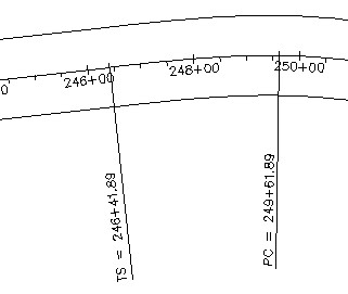
We will use the last entries to complete curve 2. The next element is a line (or tangent) segment leading up to a spiral curve. The end of the line is therefore the TS or Tangent to Spiral station. This station is 246+41.89, as seen in plan view figure below.
The line (tangent) segment is entered as shown in this figure below.
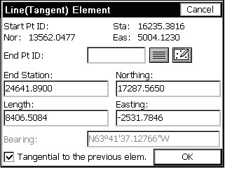
Note that the computed bearing of NW 63.4137 should be compared with the plans as a crosscheck. After clicking OK, we are now ready to enter a spiral curve to the right. Click Add at the main dialog and choose Spiral-Curve-Spiral, as shown in this figure below.
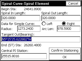
The easiest way to enter a symmetrical spiral into and out of a circular curve is to specify direction (left or right), enter the Spiral In Length and Spiral Out Length (one of which can be zero for non-symmetrical spirals), radius of the simple curve and arc length of the simple curve.
Another option is to enter the Central PI Station and Bearing Out as a substitute for the arc length. This next figure shows the result of the entry.
For spirals, if you remember to fill out the upper 3 lines, everything else is calculated, including the Central PI Station. If you press Confirm Stationing, you can verify the TS, SC, CS and ST stations and coordinates as shown in this figure.
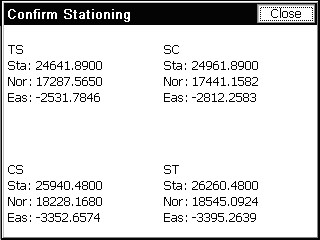
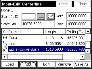
Note that we have got into negative coordinates for the Eastings. Press Close to return, and then press OK. See the spiral-curve-spiral element added to the list (see Figure 6-36).
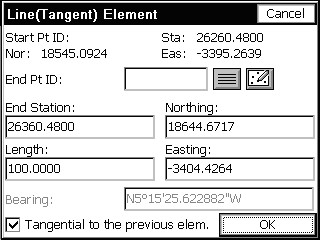
Lastly, we will finish our centerline by adding a short 100-foot segment. In this case we fill out the Length dialog box within the Line (Tangent) Element dialog, as shown in the next figure.
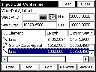
The final three elements appear in the next figure. Click Save As to store.
Starting on a Curve, and Compound and Reverse Curves
Highway Centerlines will sometimes start on a curve. They can be entered if you know the coordinates for the beginning point, radius and point of tangency of the first curve. Otherwise, you must enter a short tangent segment to precede the curve. Consider the following centerline data for three elements.
|
|
Station |
Northing |
Easting |
|
Start Pt. |
20000 |
69179.6111 |
306316.6870 |
|
Radius |
|
69165.0111 |
306316.6870 |
|
PT |
|
69165.5660 |
306331.2765 |
|
|
Arc Length |
Delta Angle |
Radius |
Direction |
|
Curve 1 |
22.3785 |
87.4918 |
14.600 |
Right |
|
Curve 2 |
82.3931 |
6.4821 |
693.637 |
Left |
|
|
Length |
Bearing |
|
Line |
11.22 |
SE 8.5903 |
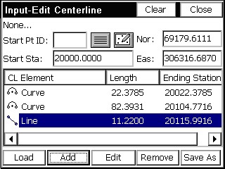
Choose Input-Edit Centerline, and fill out the starting information as shown in the next figure.
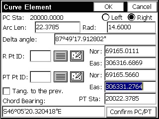
Next press Add, and go directly to the Curve option. Fill out the dialog, as shown in the next figure. Go directly to the coordinate entry dialog boxes and fill out the coordinates for the PT Pt# and the Radius Pt#. This defines the curve. Press OK.
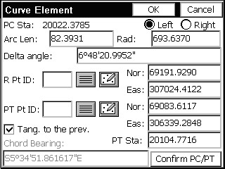
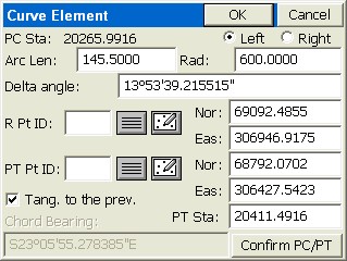
If the Curve then proceeds into another curve (e.g., for compound or reverse curves), just click Add and choose another Curve element. Since we are working on a curve that is preceded with another element, we can go directly to the arc length and radius dialog boxes, and enter 82.3931 for the arc length and 693.6370 for the radius length (see the next figure). This completes a reverse curve (first right, then left).
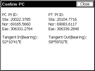
If we choose Confirm PC/PT, we can verify our tangent out bearing in advance (see the next figure).
Finally, we complete the centerline by adding a Line element with a length of just 11.22. The result is shown in this figure.
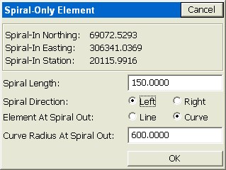
Spiral Only Example
If, from this final line segment, we chose to spiral into another curve, we could use the Spiral-Only Element. Click Add, then Spiral Only. If the spiral length is 150, to the left, into a curve with radius 600, you fill out the dialog as shown:
The centerline file can be saved and drawn using the command Draw Centerline. Shown below in the figure is the first centerline entered above, including the spiral curve.