|
Configure Base/Rover (NavCom GPS)
|
|
Configure Base/Rover (NavCom GPS)
|
Using NavCom with SurvCE
Always connect the data collector to COM1 on the NavCom receiver. The baud rates are searched after selecting NavCom in the Instrument dialog.
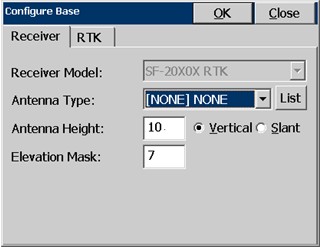
The receiver model is automatically detected. Models that start with SF are capable of Starfire, but that does not mean that the Starfire license is active. Models that are capable of RTK have “RTK” put after the model name.
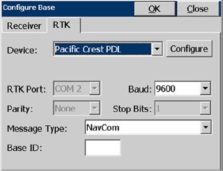
Pacific Crest PDL radios are the only RTK devices supported right now. Pressing Configure will connect to the radio, and open a dialog showing the current settings.
Receiver
Configure Base dialogs:
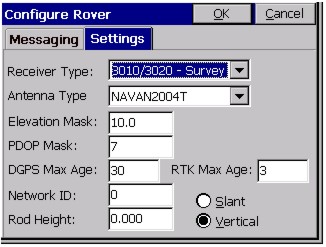
Configure Rover dialogs:
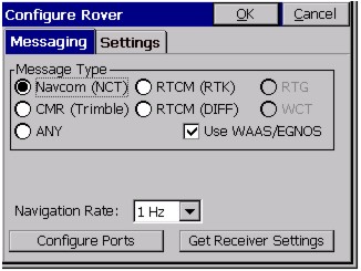
RTK
Navcom GPS handles “QuickStart”. When QuickStart is used, RMS values in Monitor and elsewhere will be displayed as “0.0” as valid numbers will not be reported from the receiver in this mode.
When configuring the rover -- even if the message “Failed to clear Navcom base position” appears -- the software will continue to configure the rover. This message should not affect the operation of the rover.
There are three sets of three LED's on the front panel of the Navcom receiver. The GPS lights indicate the quality of the receiver's GPS position reading. One or more base lights will be on if the receiver is acting as a base. These lights will also indicate the RTK message type being broadcast. When functioning as a rover, all base lights should be off. The number of link lights indicates the strength of the signal the receiver is getting from a base. Blinking link lights, or no link lights, indicates that a base has not been found. For a full description of the meanings of these LED's, read below and also consult your Navcom User's Manual.
NavCom Receiver LED Lights
NavCom receivers have three groups of LED lights labeled LINK, BASE and GPS. Each group contains a green, amber, and red light. They are very useful for quickly understanding what state the receiver is in.
GPS LED Lights
Whatever GPS LED lights are on, they blink at the rate of position calculation (1Hz, 5Hz, etc.). If the red LED is on then there are not enough satellites to calculate a position. The amber LED blinking by itself indicates that a non-differential position is being calculated. Blinking green and amber means there is a differential position (WAAS, DGPS, StarFire, or RTK Float). If the receiver has StarFire capability, then when the green LED is the only GPS LED blinking, the receiver has a StarFire position. If the receiver does not have StarFire, the single green LED indicates RTK Fixed mode. If the receiver has both StarFire and RTK ability, then a single green LED indicates either StarFire or RTK Fixed mode.
Base LED Lights
The Base LED lights blink at the rate RTK corrections are being sent. If the receiver is configured as a rover, all Base LED lights will be off. Which color of LED is blinking depends on the RTK correction format being sent. Green indicates NavCom proprietary format, amber indicates CMR and red indicates RTCM.
Link LED Lights
Carlson Software programs the behavior of the Link LED lights to depend on whether the receiver is configured as a base or rover and whether using an internal or external radio for RTK corrections. The following table summarizes the possible configurations:
|
|
Base |
Rover |
|
Internal Radio |
LED’s off |
Signal Strength |
|
External Radio |
Sent correction |
Received correction |
When using an internal radio on a rover, the LED’s show radio signal strength. Full strength is shown by all Link LED’s being on and not blinking. As signal strength fades, The green LED will start blinking then turn off, then the amber LED will start blinking and turn off, then the red LED will blink when signal is lost.
Every time a correction is sent or received when using an external radio, a Link LED blinks. The color of the Link LED that blinks depends on the RTK correction format. Green indicates NavCom proprietary format, amber indicates CMR and red indicates RTCM.
Troubleshooting
Not able to establish connection to receiver
If the data collector is connected to COM2 and configures COM1 to receive CMR corrections, the receiver will no longer recognize commands on COM1. To correct the problem, connect the data collector to COM2, go to the Configure Rover window, set the correction type to NavCom and press OK. Now connect to COM1, go to the Comm Setup window and press OK. It will then search through the baud rates to find the right one.
Unable to update NavCom firmware
A common problem people have when updating the firmware on the NavCom is they connect the computer to COM1 on the NavCom instead of COM2. They must connect to COM2 to update the firmware. The transfer will go faster if they set COM2 to run at 115200 baud before starting the firmware update utility.