|
Stakeout Line/Arc (Stake Line)
|
|
Stakeout Line/Arc (Stake Line)
|
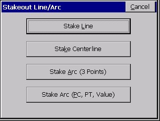
This command opens a secondary dialog where you can choose between Stake Line, Stake Centerline, Stake Arc (3 points) and Stake Arc (PC, PT, Value). Stake Line is documented below.
Stakeout Line
This command allows you to stakeout to a line between two points by guiding you to the point with a series of commands and directions.

This option is for setting out points along a line including the cut or fill, or for staking out points relative to the line. One application, for example, would be staking a pipe between two known points (inlet and outlet), where offset stakes can be set with cut/fill noted. Station Store might even be used to calculate, in advance, the inlet and outlet points based on a known station, offset and elevation. For all staking, there are configuration settings that govern the type of instructions you receive in stakeout. You should review Job Settings, Stakeout Tab under File, as well as Configure Reading and Reference Tab before staking. The dialogs are varied slightly with respect to total station or GPS equipment. Both types are documented here, illustrating the differences between the dialogs.
Stakeout Line also has a Point On Line tab that enables, in total station mode, staking of the intersect on the current line-of-sight with the specified line. This is often used to set stakes or flagging along a property line that is obscured by trees. The surveyor finds a gap in the line, takes a reading to the prism and is advised how far to Move In or Move Out to stake the line, at the current line-of-sight. The Point On Line tab also includes the standard Perpendicular method, where any measurement is used to compute the direction and distance to move to go to the point on the line perpendicular to the measured point. For GPS configurations, Point On Line offers only the Perpendicular method.
When the Stake Line routine is selected from total station mode, you are immediately placed in the Stakeout dialog, where you are asked to confirm your orientation and make sure that your current setup is correct.
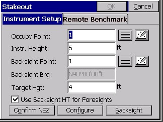
You are asked to view the Station, BS Point and BS Azi. If the three items are correct, tap OK to move on to the Point on Line dialog, or select No and you are taken to the Setup dialog to setup the instrument correctly. After the instrument is correctly configured, then you are taken to the Define Line dialog. In GPS mode, you are taken directly to the Define Line dialog to select the points on the line for stakeout or the starting point and azimuth with slope %.
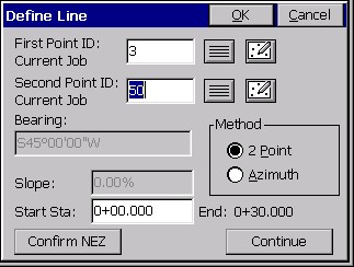
The Define Line dialog gives you these options:
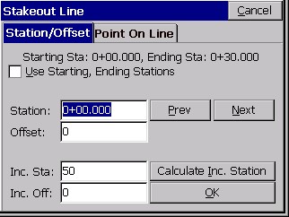
The Point on Line dialog gives you these options:
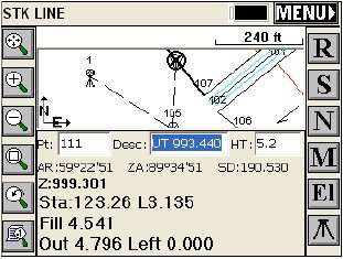
After selecting OK, the main stakeout window appears in map view. In total station mode, it will be waiting for a shot or reading. You should see your points in the map with an icon of where you need to stakeout to (the circle with the X inside).
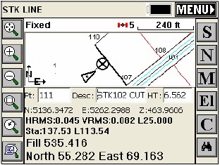
Note: that if the points defining the line are at zero elevation, the program will still report a cut and fill, in this case a cut from the GPS elevation of 463.9977 all the way to zero. If the points defining the line are at elevation, the elevation will be interpolated to determine the design, target elevation of the point to stake, and will be applied to a 0 offset or non-zero offset stakeout position.
Store a reading and the coordinates for the Stake Point and the Target Point are displayed. The delta North, East and the elevation difference (Cut/Fill) is also displayed. The Vert Offset 1 and Vert Offset 2 allow for elevation calculations based on the input vertical offset values. If Vertical Offsets are detected and a point is stored, you are prompted for additional descriptions for the vertical offsets.
If the Store Carlson Cutsheet Data in Note File has been toggled, the vertical offset(s) specified will be recorded in the .not file for the job. They will also be stored in the Cutsheet File itself, if ōSet CL Cutsheet Formatö is on. Finally, the Vertical Offset data is always stored to the RW5 file as cut/fill (cutsheet) information. If using GPS, the HRMS, VRMS, and PDOP values are also displayed, as are Fields for Point ID and point description input. After the point has been stored, you are taken back to the Stakeout Points dialog to select the next point for staking. If the Use Control File option is set under the Job Settings, you have the option of staking one of those points. If you enter in a point number to store that is the same as a point number in the control file, the point in the control file will remain unchanged. It will only modify the point in the current coordinate file. After storing a point, you are taken back to the Stakeout Coordinates dialog to select the next point. If the point being stored is the same as one in the current job file, the Point Protect dialog box appears stating that the point you chose is already used. The next available point number is listed with the option to overwrite the current point, or use the new number.
When you return to the Stakeout Line screen, after storing a point, there is a tab option for ōNext Alignmentö that allows you to define a new alignment, without exiting the command.
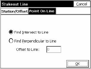
Point On Line tab in Stakeout Line
When configured for total stations, this option, which appears only in Stakeout Line and Stakeout Centerline, enables ōline-of-sightö staking of lines, where the program prompts only for in-out distance to move. This is often used by surveyors who are setting line in tree lines, moving to gaps in the trees for readings, then moving in-out along the line-of-sight and driving stakes when perfectly on line. It is useful for any line or boundary staking, such as propery lines, right-of-ways and construction lines. When configured for total stations, there are 2 methods: Intersect and Perpendicular. For GPS, there is only Perpendicular.
Total Stations: The ōOffset to Lineö option ghosts out when the ōFind Intersect to Lineö method is selected. The offset option is available when the Perpendicular option is chosen.
Total Stations, Intersect to Line: The Intersect Method is used to set line by moving in or out at the current line of sight. A major application is setting line where the line is largely blocked by trees or obstructions, and you must set the line in gaps where you do have a line of sight.
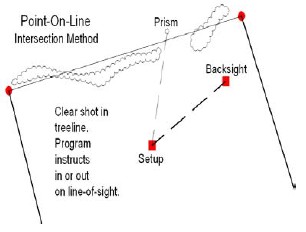
In the Intersect mode, the first screen always displays the target point on the line, (or the extension of the line), perpendicular to the setup or station point. When the first reading is taken, the program will display the In-Out distance to the line along the line-of-sight.
When staking a line defined by points with zero elevation, the Cut or Fill values will stay display but should be ignored. Notice that the screen expands by pressing the down arrow key, showing more graphics.
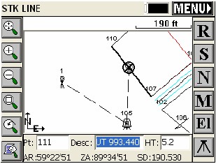
Total Stations/GPS, Perpendicular to Line: When configured for the Perpendicular to Line method, the program will show the direction and distance to move to find the nearest point on the line to the measured point. The instruction received (In/Out versus North/South or Azimuth/Distance) will depend on the setting within Configure Reading.
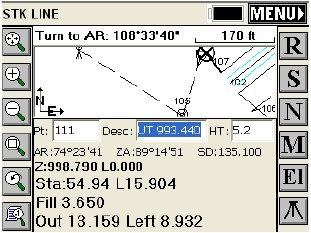
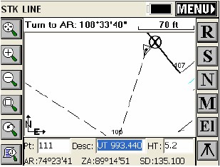
Shown above is the expanded view generated by pressing the down arrow key. The ōTurn to ARö advice, at the top of the screen, refers to the angle to turn to intersect the defined line at 90 degrees from the instrument location. For GPS, the Point-On-Line screen instructions are similar.
Point On Line, in Stakeout Line, offers the Perpendicular method when configured to GPS and both Perpendicular and Intersect methods when configured for total stations. It will default to the last method used (Perpendicular or Intersect) when set for total stations.