|
Cross Section Survey
|
|
Cross Section Survey
|
This function collects as-built cross sections of roads or other alignments and stores them as points. The descriptions of the points will store the station and offset. The station itself can be set to automatically round to the nearest 5, 10 or other station interval (eg. a shot at 179+98.23 would round to 180+00 if a rounding of 5 or 10 is used). The information can be stored into a “.not” ASCII file in addition to the points themselves, if store to Note file is turned on. You can save the cross section data to a cross section file in .SCT or RAW/Geodimeter format and you can output a cutsheet file which compares existing grade to a design grade. Cross Section Survey can also be used simply to verify your current station and offset as you move along a centerline using GPS or taking total station shots.
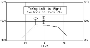
This routine is often combined with office software to check as-built road cross sections against desired grade and to calculate quantities for payment. The field crew begins by taking shots along each desired cross section, as shown in this figure.
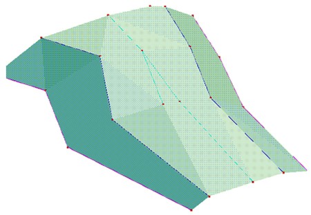
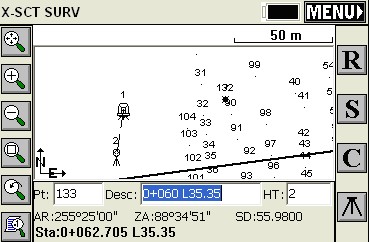
If, for example, four sets of cross sections were taken from station 0+75 to 1+50, the points would appear as shown in the plan view below, and the 3D view shown below that. There is an option to turn off point number storing, in which case the shots can still be stored to a cross section (.sct) file and report file (.txt).

Here, below, we see the 3D view of this area.
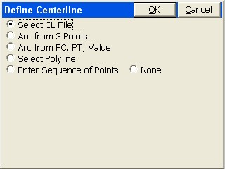
The command begins with a screen where you select the method for defining a centerline.
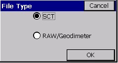
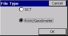
The next screen allows you to choose whether or not to store a file summarizing cross section data. Because the SCT method requires that you choose an alignment, the option for no alignment (“None”) only applies to the Raw/Geodimeter method, in which case a named file is required. Except for this case of option “None”, the Section output file is optional because the information will be stored with the points. When you click Select File, you have two file type options when using a horizontal alignment.
The Raw file format is a design that is compatible with the old Geodimeter section file format, and includes special prompting for job type. It is discussed in detail below (see the discussion of “None” as centerline option). It leads to a different set of screen options than the SCT format.
Unless you are looking for Geodimeter file format compatibility, you should consider storing a section output file in the “.SCT” format, since it can be converted, using Road Utilities, to LandXML form and then imported to several different roading software packages for plotting and computation of volumes. The “.SCT” section files can also be used directly for volume calculations with Carlson Roads, Leica Site Manager, Topcon Topsite and SurvCADD. You can also set the rounding—here, a rounding of 10 units (feet or meters) has been selected. The station and offset can also be stored as the point description and as a note file, if the lower options are clicked on.
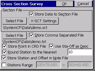
Note that the rounding is fully automatic. If you choose a 5-unit rounding, and are targeting station 0+75, but take a shot at 0+77.93, it will round up to 0+80.
Before collecting the cross sections, it is important to click X-SCT Settings near the top of the dialog, and set the stations you wish to capture. This way, if the station rounds, per the above screen, to a station that doesn’t exist in your list, you are warned before proceeding with storing. This list also includes the left and right “tolerances” for the offsets, which will lead to warnings if you exceed that distance from centerline. If you set a tighter “Station Tolerance” in X-SCT Settings (option Edit) than the “Rounding” Tolerance, you will be warned even though the rounding is correct. These tolerances should match, for consistency. In the screen shown below, station 6+60.000 has been added as a special station. Clicking the first line (0+00.000-10+11.570) allows you to set the standard interval, and the additional stations in the list would be for special stations in addition to the standard interval.
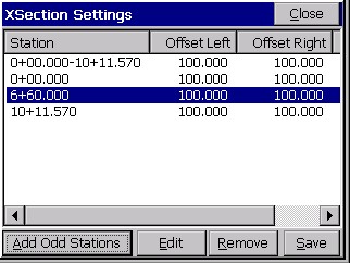
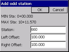
The below, smaller dialog appears when you tap Add Odd Stations, shown in the above figure.
With the first line highlighted, selecting Edit leads to the settings options for the full range of stations.
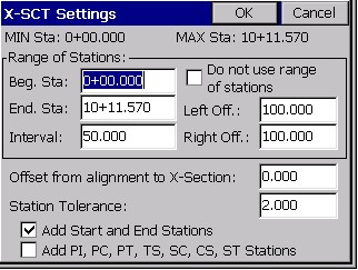
With an interval set of 50, and Start/End Stations turned on, and the special station 6+60 added, the program will only expect you to capture stations at 50 units intervals starting at 0+00 through to 10+11.570, but also including 6+60. The Offset from alignment to X-Section option let’s you, in effect, use an alternate, parallel centerline at a left (negative) or right offset from the main centerline. Unless the Raw/Geodimeter method is used, a station “warning” screen is used if the rounded station is not in the list or pre-selected stations. The “Station Tolerance” option will let a capture of station 75 round to 80, but since 80 is not in “the list”, you will be warned before storing. A station of 55 would round to 60, which is in the list, leading to no warning screen. Since the rounding was set to 10 in this example, data collected at 45 to 55 would round to 50 (station 53 would not round up to 55), and therefore only “even 10” stations will be collected to begin with. So the additional “Station Tolerance”, which rounds the collected station data to the listed stations, will not activate. Had we permitted rounding to the nearest 5 station, then 55 would round up to 60 and store without warning.
When OK is clicked from the Cross Section Survey dialog, the program immediately proceeds to a point collection mode, with continuous presentation of station and offset (if running GPS or robotic total stations).
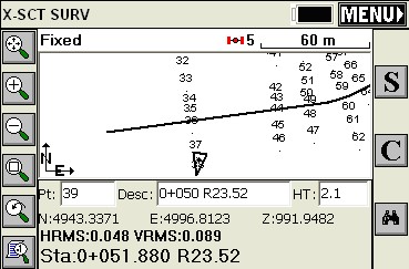
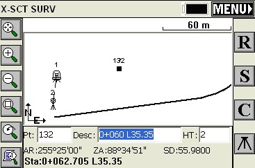
Here, your options are R for read, followed by S for Store, or simply Enter to Read and Store. The backsight icon can be pressed to set a new occupied point or backsight point. Note that we have a very “busy” screen of points. If you just want to see your setup, backsight and last point that was measured, press Alt F. This produces the screen below. You will stay in this mode until you press Alt F again and toggle back to the presentation of all points.
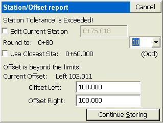
If a shot is taken that doesn’t round to a station in the list of “approved” cross section stations (X-SCT Settings), then a warning screen appears.
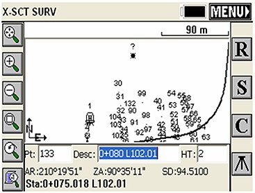
In this warning screen, we have exceeded the tolerance on two accounts: We round to 0+80, which is not in the list, and our offset is 102.011 left, which exceeds our anticipated maximum offsets of 100 left and right.
Points Store with Station/Offset Descriptions, as shown below:
|
29 |
1+25 |
L23.58 |
|
30 |
1+50 |
L33.24 |
|
31 |
1+50 |
L19.39 |
|
32 |
1+50 |
R1.98 |
|
33 |
1+50 |
R18.12 |
The “cutsheet” file, which is comma-separated, would appear as follows if presented in a tab-delimited form:
|
#Point ID |
Station |
Offset |
Elevation |
Description |
|
29 |
1+25 |
Left 23.5759 |
991.2901 |
1+25 L23.58 |
|
30 |
1+50 |
Left 33.2363 |
989.9193 |
1+50 L33.24 |
|
31 |
1+50 |
Left 19.3923 |
996.8921 |
1+50 L19.39 |
|
32 |
1+50 |
Right 1.9816 |
998.2340 |
1+50 R1.98 |
|
33 |
1+50 |
Right 18.1201 |
997.0731 |
1+50 R18.12 |
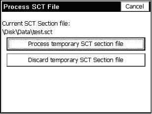
When you exit the routine by clicking Menu from the data gathering screen, and have Store SCT file turned on, you will be asked if you want to “process” or add the last shots you collected to the named SCT file. You have the choice to “Process” (use the data) or “Discard”.
The program will even keep the section data “on file”, so that if you Cancel the above screen, and re-enter Cross Section Survey, you will be prompted again whether to save (process) or discard the cross section data collected earlier.
Options When Storing in Raw/Geodimeter Format
Different options present themselves when the Raw/Geodimeter Format, or File Type, is chosen.
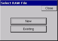
When Raw/Geodimeter is selected, a distinct set of screens are obtained. This particular format was adapted for highway departments and survey companies that had built cross sectioning practices around the Geodimeter format. This method requires that you enter the station (chainage) being surveyed, and only uses the centerline position to advise you on your station and offset. A horizontal alignment is not required. The program detects the selection of this format, and before proceeding, opens with a starting screen where job-based information is entered.
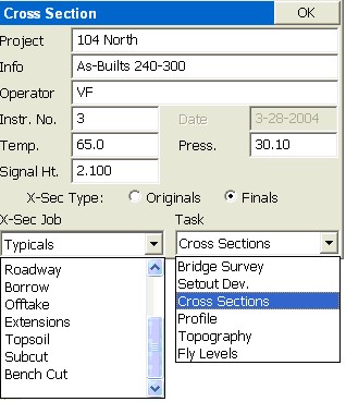
There are pre-set job categories and tasks, which save into defined number categories in the old Geodimeter raw file format. Whereas the SCT method recognizes the station you are on and automatically rounds to it when you are within tolerance, the Raw/Geodimeter method requires that you click the Station button, and set your target station for collection of cross section data.
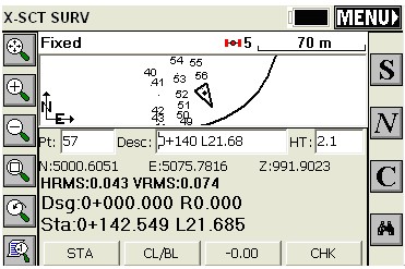
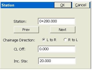
Then you proceed from the current location to the target station. In fact, although the points that are stored may contain station and offset descriptions, the data stored to the raw file pays no attention to the centerline information. The station and offset on the screen act only as a check on your current location. The direction of taking the sections, (L to R or R to L), is important and is set by specifying “Chainage Direction”. Unlike with the SCT format method, pressing Menu to exit does not store the data, but instead the data is automatically stored as you go, as a series of 37 (N), 38 (E) and 39 (Z) record types (Geodimeter format), with header line records, as shown below:
50=XSEC1
54=104 North
0=As-Builts 240-300
53=VF
90=2
97=0
51=3-28-2004
56=65.0
74=30.10
55=3
96=2
6=2.100
80=280.000
91=1
37=5105.857
38=5069.091
39=991.905
37=5104.091
38=5074.931
39=990.724
Starting left to right, the data points begin with a 91=1 record. A right to left section would begin with 91=2. When you “cross 0” or are on the centerline or baseline, you click the CL/BL button which sets a 92=1 record for centerline and 92=2 for baseline, and the next shot is the centerline/baseline shot. If you select the “-0.00” button, this indicates whether the next shot is a tie-in (catch) or extension beyond the tie-in. This sets a 93=1 record for the catch and 93=2 for the extension prior to the subsequent coordinate record. In effect, you tell the program where the centerline or baseline is by shooting that point. Then the station and offsets of the shots for that cross section are determined relative to that center-of-alignment shot. It does not use a horizontal alignment combined with rounding to determine the station and offset of the shots (like the SCT method does). You tell it the station, the direction of measurement (left to right or vice versa) and you tell it which one is the center shot. This is why the Raw/Geodimeter method is the only method that works with no centerline (the “None” option). For each section, you tell it the station and center shot, and all other measurements are used to determine the left and right offsets relative to the center shot. If the L to R method was used, shots before the center shot are on the left, for example, and their offset is determined by the inversed distance to the center shot. The centerline file or other form of horizontal alignment, if selected, is academic and only used to advise you on your current station and offset. The CHK button will allow checking into known points to be sure that tight coordinate control is maintained. N moves onto the next station as defined by the interval set using the Sta button.
Note: The .SCT file method is the standard Cross Section Survey method. The RAW/Geodimeter method is a flexible routine designed to adapt to customers who have built their cross section processing systems around the Geodimeter raw file format.