|
Slope Staking
|
|
Slope Staking
|
The slope staking command calculates and stakes out the location of the “catch point” where fill slopes or cut slopes contact the original ground. The slope staking command will also set offset stakes to the catch point and will produce a report of the slope stake information. The location of the slope stake is dependent on the position of the “pivot” point where the slope begins and on the slope itself (eg. 2:1, 3:1, 4:1, etc.). Slope stakes are typically used in highway work, to locate the toe of slope or top of cut. If design file information is available for the road template and profile, then the slope stake routine will calculate distance and offset information for all “break points” on the template from the slope stake itself back to the centerline. This also applies to slope staking conducted by section files, and descriptions associated with the break points on templates and/or sections are identified by name in the slope stake report.
There are “rules” for slope staking. The slope stake is measured from a pivot point, which is user-entered, or starts at the centerline itself in “point-defined” alignments, or starts at the last template point before the cut or fills when templates are involved, or starts at the left and right end-points of sections when using section files. Note that in the command Template Stakeout (which works with both sections and templates), slope staking can be initiated from any desired point. This allows for slope staking of interior, central median catch points and slope staking of any side of an eventual divided highway, being built in stages. Slope staking can be interval based, or accomplished based on where you are standing right now, independent of station interval.
Although office plans may predict the position of the catch points, slope staking is necessary to accurately determine the catch points based on actual field conditions. Slope stakes are often set at an offset to the actual catch points, since stakes at the precise top of slope or bottom of fill are likely to be knocked out by earthmoving activity. Furthermore, slope stakes are often marked with information on the slopes and distances in toward centerline or in towards the building pad or other feature. The information on the slope stake is often written in “progressive” form: distance and slope from offset stake to slope stake, distance and slope from slope stake to outside shoulder, distance and slope from outside shoulder to edge of pavement, on into centerline. Thus, the slope stake, placed safely beyond the area of construction, tells the story of the cuts and fills in towards centerline or towards the center of the work.
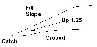
Catch points for both cut and fill are shown in the typical section graphics below. See these two figures.
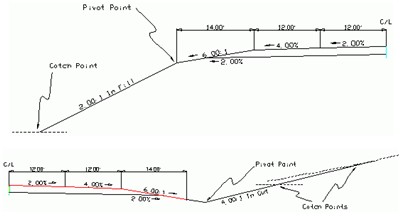
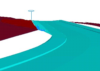
Note in the “cut” example above (bottom figure) how the catch point may be closer or farther from the pivot point based on the slope of the original ground. With flat ground at virtually the same elevation as the centerline of the road, the catch is found approximately 15 feet from the pivot point in the base of the ditch. But with ground sloping slightly uphill, it takes a full 30 feet or so to find the catch point. The program helps find the catch quickly by modeling the surface of the ground with each shot taken. Thus, by projecting the ground slope outward, the program advises the user how far to go to find the anticipated catch point. Unless the ground slope changes dramatically, the catch point is usually staked within just a few tries. With GPS, the process is even more automatic, since the ground elevation is being computed continuously as you walk toward the catch point. No “shot” has to be taken until you are positioned right on the catch point itself. This next figure shows a cut condition slope stake in 3D. The “catch” is located at the top of the cut.
Four Methods of Slope Staking
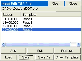
Note: Whenever the Road Design File options is selected, templates can be selected as a single “TPL” file, or as a series of templates organized as a “TSF” file (Template Series File). The TSF file can be entered within Road Utilities. If the left pavement lane of a road expanded from 10’ to 20’ for a passing lane, from station 1100 to 1200, you can create two templates, Road1 with the 10’ lane and Road2 with the 20’ lane. Then if you create the Template Series File shown below, the program will auto-calculate a 15’ left pavement width at station 1150. This same feature can be accomplished by using one template and applying a Template Transition File, which instructs on the changing dimensions of portions of a single template. Unlike the Template Series File, the alternate Template Transition File can only be created at the office using SurvCADD, Carlson Roads or Carlson TakeOff.
One advantage of the design files method is that since each template point has an “ID”, the slope stake report will include information to locate all ID’d template points from the slope stake back in to the centerline. In this way, the entire road can be built from the information marked on the slope stake, which is placed outside the construction area at a user-specified (eg. 5’) offset to the actual catch point.
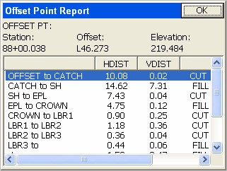
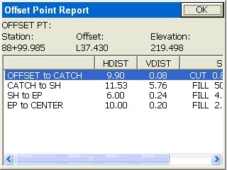
A report might appear as follows:
|
|
HDIST |
VDIST |
SLOPE |
|
OFFSET to CATCH |
5.02 |
-0.17 |
CUT 3.4%, 29.5:1 |
|
CATCH to PIVOT |
32.20 |
16.10 |
FILL 50.0%, 2.0:1 |
|
PIVOT to SHLDR |
14.00 |
33 |
FILL 16.7%, 6.0:1 |
|
SHLDR to EOP |
12.00 |
0.48 |
FILL 4.0%, 25:1 |
|
EOP to CL |
12.00 |
0.24 |
FILL 2.0%, 50:1 |
This is sometimes referred to as a “progressive” report, since it lists the incremental information from each break point to the next, going in towards the centerline. In some areas, the stake is referred to as a “story stake” or “progressive story stake”, because it tells the whole story of the gradework. The program is able to identify the names of the break points (eg. “SHLDR” and “EOP”) because the templates used by the program must have pre-defined IDs for all break points. Specifically with office-defined templates where cut conditions can have downslopes for ditches followed by upslopes, the program will auto-detect whether to pivot into fill or to create a cut condition, and pivot from the ditch line.
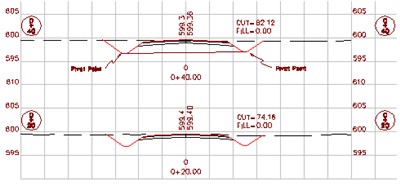
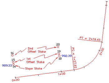
Shown are stations 0+20 and 0+40, with the pivot points for slope staking identified on station 0+40. For the section approach to work, the left-most point in the cross section must be the left pivot, and similarly, the right-most point in the cross section must be the right pivot point. The section should only be entered from pivot left to pivot right (the “designed” catch points should be dropped). But since the interior section points have no bearing on the slope staking, they can be omitted, too. So in the case of station 0+40, a 2-point cross section could be entered, consisting of pivot left and pivot right. That 2-point section is also shown in the graphic above. It is just as effective for slope staking as a section containing all the break points between pivots. The one exception is if you have entered descriptions for your section points, you can obtain a progressive slope stake report, just as with the templates, as shown below (metric distances). Note that if descriptions do not exist, the report leaves them out. Section-based slope staking requires selection of a centerline file and field-entry of the cut and fill slopes.
Section-based slope staking is useful when the pivot points for stakeout vary unpredictably and don’t conform to a fixed template. Section-based slope staking has 2 advantages. First, all sections can be entered in the office as 2-point sections (left and right pivot), minimizing field paperwork and reference material. Secondly, odd stations can be staked out (eg. station 0+27.5), since the pivot points can be straight-line interpolated by the program.
Note: Section files can be used for slope staking within the command Template Stakeout. In this routine, you can choose sections or templates to stake, and you can pick any point to slope stake from—so any point on the section can become the pivot point. The advantage of slope staking by section file within Template Stakeout is that you can pick any point (greater flexibility). The advantage of slope staking by section file within the Slope Staking routine is that it automatically uses the left and right end points of the section as pivot points, which means less screen picks are involved (greater speed).
Section files may be entered in Road Utilities, or in an external program such as Carlson SurvCADD, Roads or TakeOff.
Choosing the Slope Staking Method
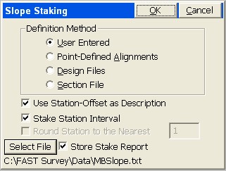
When Slope Staking is selected, you are presented with a Definition Method screen, where you choose among the 4 methods of Slope Staking: User-Defined, Point-Defined Alignments, Design Files or Section Files. The application of these methods is discussed above.
When you click out of the opening dialog that offers the 4 methods of Slope Staking, you obtain additional input screens.
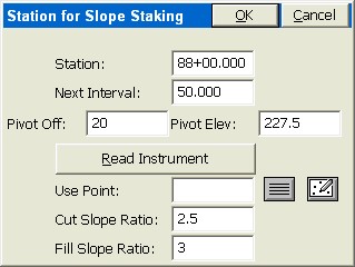
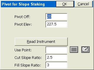
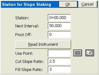
At each station, you can enter a specific pivot offset, pivot elevation and the cut and fill slope ratio that governs. Pivot offsets should be entered as positive numbers even left of centerline, since the program will detect which side of centerline you are on from the first total station or GPS reading. The program will take the absolute value of the pivot offset entry, in any case. You can obtain the position to stake from “Read Instrument”, which calculates the station, offset and pivot elevation from a measured position. Or you can enter a point number to obtain a station, offset and pivot elevation.
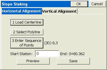
Though this is the classic use of the Point-Defined option (using points), slope staking can be conducted from a single centerline and single profile or from a picked 3D polyline. Points can be selected by number or picked directly off the screen.
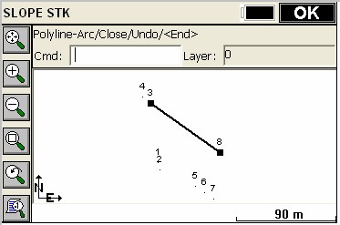
When a new horizontal alignment is selected by 3D polyline or point method, the program will ask if you wish to overwrite any existing vertical alignment selection. The typical answer is yes—you want it for both, and you are ready to stake any station at any interval based on user-entered slopes. Think of points 8 to 3 as the flow line of a ditch with steep side slopes, and the goal is to lay the slopes back at 4:1—a perfect application for Point-Defined Slope Staking.
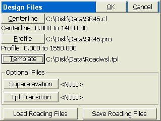
Centerlines, profiles and templates can be made using SurvCE. Note that templates can be either single template “.tpl” files or multiple templates with transitions in a Template Series “.tsf” file. If the roads have superelevation, the “super” files can be made in Road Utilities. If template transition files are to be used for lane changes, then this file type must be made using external software such as SurvCADD or Carlson Roads. Note that “sets” of Roading Files can be saved and loaded using the buttons at the bottom of the screen.
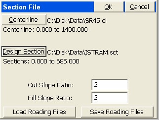
The Section file (which has an “sct” file extension) can be entered in Road Utilities or impored from the LandXML format using Section File Conversion, also in Road Utilities. Note that for all roading design files, there is no requirement that starting and ending stations (chainage) match. All that is necessary is that they have a station range in common (in the above case, 0 through 685 is common to both the centerline and section files). Roading File sets (as in the above MB.cl and Xsec.sct files) can also be saved to a named set and then re-loaded later for convenience.
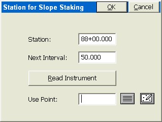
Setting the Station and Interval for Stakeout
The next screen sets the station to stakeout and the interval. This screen’s options are slightly different depending on your method and whether you have turned off the Station Interval option. In effect, there are 8 ways of going into Slope Staking: 4 methods times 2 interval options (on=fixed station/off=fluid, real-time). You also have 3 more methods if you include the Template Stakeout routine which offers Slope Staking by Section, Template or User-Defined, all fixed station. The User-Defined station interval dialog has already been discussed. But if you click off the “Stake Station Interval” option and slope stake “where you are”, the User-Defined dialog is simplified.
Note there is no “Station” and “Next Interval” option—it will just use the same offset and elevation at all points along the centerline as you move. This non-interval method could be called “real-time” slope staking. You are freed of the constraints of staking a fixed point at a specified station.
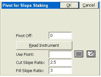
The Pivot Offset should be entered as a positive number—the program will automatically detect whether you are on the left or right side of the centerline. The screen is exited by pressing OK.
The Alignment Point method has its own pair of “follow-up” screens for the location to stake.
For flow line or V-ditch staking, a 0 pivot offset would be entered from the point-defined alignment. If the ditch were a trapezoidal ditch with a 2 meter bottom width, and the alignment was the centerline, each side of the ditch could be slope staked using a pivot offset of 1 (1/2 of the ditch width from center to pivot point).
Both the Road Design Files and Section Files methods go straight to the navigation (stakeout) screens if no interval is selected (Stake Station Interval turned off). The pivot offset is built into these methods based on the “rules” outlined earlier -- you stake from the pivot to cut or fill in templates, and from the extreme left and right points of cross sections.
Slope staking cannot occur outside the station range of the horizontal alignment. If your horizontal alignment runs from station 0 to 308, you can’t stake station -10, either by interval method (naming the station) or by the non-interval, fluid “where-you-are” method.
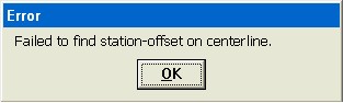
In live stakeout mode, you will get “Off Centerline” when beyond the range of the horizontal alignment.
All paths lead on to the navigation or stakeout (some call it “set out”) screen.
The Navigation (Stakeout) Screen
When configured for GPS, the navigation screen then appears.
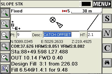
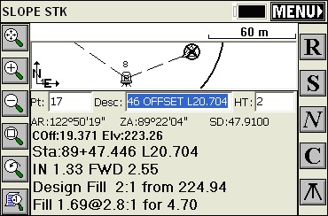
Note that because the GPS reads continuously and models the ground surface, the program calculates immediately where the catch point (the circle with the X) is located. You simply walk right to it. If the ground goes uphill or downhill as you approach the point, then the X will move closer or move away, until you are right on it.
As you get closer to the point (within the stake tolerance distance) the program will present a bullseye screen.
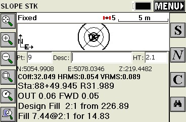
When you are satisfied with the accuracy of the slope stake position, you then touch S for Store (or press Enter to take the shot). In this case, the fill rounds to 2:1 so its time to drive the stake.
Interval and Non-Interval Methods Impact Stakeout Screen
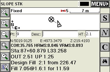
The stakeout screens above are for the interval method. In the non-interval, “fluid” slope staking, where you can drive the stake anywhere, the “Forward-Back” portion of the screen becomes vertical “Up-Down”. This is not referring to up-down station but up-down vertically. In this fluid stake-out mode, you simply move in or out from the centerline to set the slope stake—there is no correct or incorrect forward or back station. So the program instead reports the vertical up to the fill slope above you or down to the cut below you.
If you are moving out to the catch point along the ground, you would get a report of “Up 1.25” or some such number, and the “Up” amount to the ground would decrease as you approach the catch. The actual stakeout screen would appear as shown below. Note that some surveyors will watch the lower line (1.6:1 for 11.59) and just keep moving out until they see 2:1 (or the desired slope) and drive the stake. This is fast, but slightly less accurate. Because of rounding, you may be setting 2.04:1 or 1.96:1 (good enough for many types of work). Others will watch the “UP” value decrease to 0 and drive the stake, which is the most accurate method along with watching “OUT” decrease to 0.
Storing the Slope Stake and Offset Stake Points
When S for Store is pressed, you may store the actual slope stake point. You can also store a first offset point (since the slope stake itself can be removed by construction). The slope stake information is typically written on the first offset stake. Then you can also stake a second offset point, to obtain “line” to reset the slope stake if it is knocked out. The first and second offset stakes provide a direction back to the slope stake. When the slope stake is set, the program prompts for setting the first offset stake. When the first offset stake is set, the program prompts for setting the second offset stake. Both offset stakes are optional.
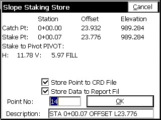
The storage of the slope stake points is an option turned on by clicking “Store Point to CRD File”. With this clicked off, you can simply slope stake and avoid storing any points. The Description for the point will default to the station and offset, if Use Station Offset as Description is turned on within the initial screen. Otherwise, the description will be blank as shown below, or will default to the previous description. Slope Staking will not respond to settings in Configure Reading for the Height/Description prompt screen. If you are using a named “Report File” (set in first slope stake screen), you can still control at the point of staking whether you choose to append data to the file by clicking on or off “Store Data to Report File”.
When Enter or OK is pressed, you are prompted for whether to stake the first offset stake.
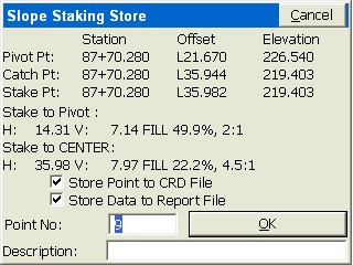
If you are doing “User-Defined” or “Point-Defined Alignment” methods, you are shown the horizontal distance and vertical difference to the pivot point, which can be written on the Slope Stake. Additional break-point information appears if you are using the “Design File” or “Section File” method. If you trust that the Slope Stake will not be knocked out, then you are done—no need to set an offset stake.
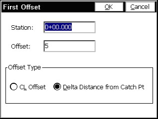
Pressing OK leads to the prompt to set the first offset stake. If you choose to set the first offset stake, then you can set the offset distance.
Press OK and then you are in a standard stakeout screen. The offset point is a fixed location and the stakeout procedure is similar to point stakeout. This leads to a report of information that can be written on the Slope Stake. Finally, you will be prompted for staking out a second Slope Stake, to establish “line.” After the first offset stake is set, and before the prompt for the optional second offset stake, a summary screen will appear. If you have used the Road Design File or Section File methods, you will be presented with every break point into centerline.
Finally, you will be prompted for staking out a second Slope Stake, a more rarely used option whose purpose is to establish “line” (the direction) from the first offset stake to the slope stake itself. This permits accurate replacement of the slope stake when it is knocked out by construction activity.
Note: When using Road Design or Section Files in Slope Staking, setting the first offset point is the recommended procedure, as it produces the full report, referenced to cross section and template IDs, for all break points all the way into the centerline point.
Procedure for Slope Staking with Total Stations
The procedure is nearly identical for Manual Total Stations, except that you must press R for Read (or Enter) to take shots and allow the program to begin calculating the Slope Stake position. Unlike the GPS, SurvCE cannot predict the location of the target slope stake point until at least one measurement is taken.
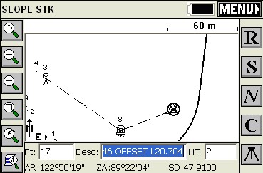
Note: When using either GPS or total stations for slope staking, you can obtain more graphics and less screen information by pressing the down arrow key. It literally has the effect of bringing the graphic screen down (see below). Pressing the up arrow key will pull the screen back up and show the full text. This works in all modes except GPS Simulation, where the up arrow moves the cursor faster, down arrow slower.
The Slope Stake Report and Writing on the Slope Stake
Surveyors doing slope staking have the option to write the information on the stake as each is surveyed, or to come back at a later time, refer to the slope stake report, and write on all the stakes after the surveying is complete. The slope stake report file is a comma-separated “.txt” file, configured in Job Settings, Stakeout, Set Cutsheet Format, which might appear as follows if formatted in Excel or another spreadsheet form:
|
#Des Sta |
Des Off |
Des Elv |
Staked Sta |
Staked Off |
Staked Elv |
Desc |
|
1+00.000 |
L33.849 |
998.075 |
0+99.966 |
L33.453 |
998.075 |
Catch Point |
|
1+00.000 |
L38.849 |
------ |
1+00.019 |
L38.866 |
998.15 |
First Offset Point |
OFFSET to CATCH, 5.01, -0.07, CUT 71.6:1, 1.39%
CATCH to PIVOT, 23.849, 11.925, FILL 2:1, 50.0%
Armed with this information, the user could write out the slope stake.