Template Stakeout is one of four major commands used in highway work. This command is designed to stakeout specific stations and offsets along a centerline. For example, if your goal is to stakeout the break points at station 87+80 on a given road centerline, you would use Template Stakeout. Template Stakeout, therefore, is used primarily to lay out road surfaces for construction. Template Stakeout is typically used to set cut and fill stakes or “blue tops” at specific stations and offsets. The elevation used to determine the cut or fill at each offset is derived from either design files (the template interacting with the profile and centerline) or from cross sections or from sections that are “cut” from alignments. At any specific station, you will be guided to the desired offset and will get a cut or fill. By contrast, if the goal were to simply set random cut and fill stakes along an alignment, at no particular station or offset, then the command Elevation Difference would be used. If the goal is to stake out the “catch” in cut and fill, where cut slopes and fill slopes meet existing ground, then Slope Staking would be used. The fourth, major highway-oriented feature is Cross Section Survey, which is used to gather “as-built” information on a road. In this command, you take cross sections of data points along the road, at random or specific stations. In summary, Slope Staking starts the cut and fill work, Template Staking directs the precise roadbed work and fine grading, Elevation Difference acts as a quick grade check, and Cross Section Survey produces the final confirmation of the as-built road for payment and certification.
Defining the Road
The first dialog that comes up when you select Template Stakeout is where you define the road by selecting one of the following options.
- Design Files: In Carlson SurvCE, design files include templates, centerline, profile and and optinally, superelevation and template transition files. If you wish to “clear” a file such as a superelevation file, just click it and choose Cancel. The definitions for each of these files is covered in their own sections of this manual. Design files are recommended for subdivision streets, access roads and simpler highway designs.
- Section Files: Sections are made up of simple offsets and elevations that can have descriptions such as “EOP”, “DL” or “SH” and must be accomanied by a horizontal alignment file (centerline). Every cross section is a “snapshot” of the template at a given station. SurvCE supports using mulitple surfaces simultaneously in Template Stakeout by using multiple section files or by extracting the section for each surface when all surfaces are within a single file. Each surface can exist on its own layer with its own color for easy identification while in the Template Stakeout dialog. For complex designs, with non-conforming intersections, transition lanes, special ditches, etc., it is recommended to use cross section data if available.
- Cut Section from Alignments: Provides the ability to extract cross sections directly from 3D polylines that exist within SurvCE. The first thing you need to define is the horizontal and vertical alignment files. These form the basis for cutting the sections and determining left and right offsets from the horizontal alignment or centerline. The centerline-defining screen is similar to the screens found in Stakeout Line and other commands.
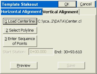
This just starts the process. With both horizontal and vertical alignments defined, click OK. You will then be asked to define a template point alignment (TPA) file. In this process, you must either pick or identify by point number or file each alignment “pair” (H and V) that define an edge-of-pavement or other feature of the sections. It takes a 3D polyline, or a pair of horizontal and vertical files, or any mixture of points, polylines and files, to define a single offset feature.
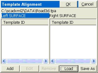
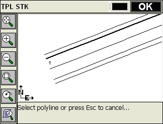
Click on Left Surface, for example, then Click Add. This brings up the same screen used to define the centerline. If you have a drawing of 3D polylines (brought in as a DXF file, for example), it is very easy to illustrate this command by the Pick Polyline option. When chosen, you obtain the next screen, where you can pick the EP.
Now click OK, say Yes to Overwrite vertical alignment (if the polyline is 3D), and simply OK the screen (no need to save the file as a named alignment). This brings up the name template ID dialog.
Repeat for the outer polyline (SH, left side), then for the EP on the right side and SH on the right side. You now have a centerline and 4 offset alignments from which to cut sections. When you get the full contingent of alignments defined, click Saveas to Save the TPA file. Now any design offset at any station will be automatically interpolated, and normal template/section stakeout can proceed.
- Save Roading Files: This button will save the selected set of roading files as an RDF file for recalling later.
- Load Roading Files: This button loads all of the files previously save to an RDF file. The files must still be present in the original locations.
Interpolation
If descriptions are provided, “intelligent” interpolation is performed between similar descriptions on slope transitions or widening lanes as well as vertical curves for all methods described above.
Template Stakeout
The next screen is the heart of the program. Here is where you select the station and offset to stake out. You can even launch into a slope stake and then return to stake out other template points.
- Settings: The “Additional Stake Stations” that appear in the List are set in the lower portion of the dialog. The Vertical Scale option will allow for “exaggeration” of the vertical on the template graphic. Though defaulting to 1, we can double the exaggeration by setting this to 2. In fact, an exaggeration of 5 works fine for the “demo.tpl” template file. The “Next Station Method” governs how “N” for next, from the stakeout graphic screen, moves you up. When set to “None”, N for Next will stay put until you change your entries. But if set to “Next Offset (Left to Right)”, Next will stay on the current station and move to the next offset. The “Next” in the dialog below, however, always increments the current station by the next station in the List. Don’t confuse the Next button on this screen, with the N button on the graphic screen to follow, which is influenced by “Settings”, and moves you along after you complete each point stakeout.
- Station: The value of the Station to Stake.
- Interval:The horizontal distance to incriment the stationing when using the Next and Previous nuttons.
- Play/Pause: This button allows the user play through the road file like watching a drive through movie.
- List: Depending on the settings and specified interval, “List” will list the defined stations including intervals and critical stations.
- List Offsets: This dialog allows the user to pick from the known offsets by a list rather than using the graphic screen below. It also allows the user to select an optional second point of "Reference" for reporting cut/fill information while staking. With this option, the selected offset and the secondary reference offset will both be reported to.
- Design Offset: Any offset can be entered, even if it is not a “break point” on the template. For example, an offset of Left 5 (-5) or Right 7.23 could be entered. For every design offset point selected, the elevation is calculated and presented. You can select the offset point from the offset list or literally pick it on the screen. The touchscreen is active in the graphic, so you can select the -12 (EP) just by picking it. Picking on the graphic screen will take you to the “Offset List” screen for verification, where you can confirm your pick by pressing Enter or selecting another offset.
- Stk Off(H): Horizontal offset from the design offset. If you enter an stake offset of 2 and the design offset point was at 12, then the stake would go in at offset 14 off of CL, but the cut/fill would refer to the elevation at the design offset location of 12. The stake offset and Off. to CL inter-react. A stake offset entry of 15 with a design offset of 12 left calculates to a setback of 3.
- [...] Button: This button allows the user to specify the horizontal and verical offsets relative to the design offset. Various methods can be used for computing the offsets based on the template or section points and their elevations.
- Off to CL: This is the total distance that the stakeout position is from the defined road centerline.
- Vert. Off (V): Vertical offset from the design elevation.
- Elevation: Elevation to be staked. This value is based on the combined design elevation and vertical offset.
- Run Slope Stake: This feature allows for dynamic slope staking in the middle of the Template Stakeout routine. This option is very useful for road staging, and also for staking interior catch points like central median ditches. When the slope stake is completed, the program returns to the main Template Stakeout dialog. Any point in the template or section can be used for running in a slope stake. You are asked to specify the desired cut and fill slope ratios. The slope can be auto-defined or user defined as follows:
Define Slope by Next Section Point: This option allows you to select the edge of the road and use the proposed design catch point for auto-dermining the slope rate.
Define Slope by Previous Section Point: This option allows you to select the proposed design catch point and then use the next point towards CL for auto-dermining the slope rate.
Extend Current Slope: This option will allow you to pick the edge of the road or catch point and use the next point towards CL to end the slope between then away from CL.
User Defined Slope: Allow you to enter the slope ratio by hand for on-the-fly slope changes.
Slopes by Template: This option extracts the slope definitions from the template file itself.
- Pivot Point: This option allows the user perform on-the-fly offsets releative to the stakeout position defined in the from end of the routine.
Stakeout Views
Template Stakeout now allows you to navigate to the point in either plan view or cross section view. Select the X-SCT/PLAN icon to switch back and forth.