|
Road Utilities
|
|
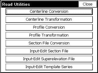
Road Utilities
|
Road Utilities include necessary routines to convert centerlines, profiles and cross sections from other formats to the formats used by SurvCE. SurvCE uses ASCII file formats for centerlines (ō.clö files), profiles (ō.proö files) and cross sections (ō.sctö files). These same formats are used by other Carlson products such as SurvCADD, Carlson Survey and Carlson Roads.
Road Utilities will also scale up or down centerlines and profiles, usually to convert between metric and English units. In addition, Road Utilities includes a command for entering a superelevation file (ō.supö), which can serve as an optional input file, and react with templates in commands such as Template Stakeout, Slope Staking and Elevation Difference. Finally, Road Utilities has an option for a Template Series file (".tsf" file), which will transition from one template to another automatically, as long as the templates share identical ōIDsö. The Template Series file can be substituted for a standard template file in Slope Staking and Template Stakeout, wherever ōdesign filesö are applied.
File Conversion and LandXML: The LandXML file format is becoming a standard encouraged by many DOTs, by Autodesk, by MicroStation and by several software companies such as Carlson, Infrasoft (Moss) and Geopak. LandXML files have a ō.xmlö extension and may contain various road design files from centerlines to profiles to cross sections. The ōheaderö lines within the ō.xmlö file will indicate what design files are included, and sometimes several files of the same type, such as three or four centerlines or profiles, may appear in the same LandXML file. As more and more software companies offer LandXML file output, this file type may be the preferred form for data exchange. Be aware that each company tends to implement the LandXML format in slightly different ways, much like DXF files for drawing data exchange were sometimes slightly different in format between AutoDesk and MicroStation, or from release to release. Therefore, if a LandXML file containing centerlines, profiles or cross section files fails to convert, it is recommended that they be emailed to Carlson Software so changes can be made in SurvCE to enable conversion. LandXML is an evolving format that is likely to solidify in the near future.
Centerline Conversion
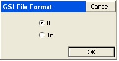
This command converts horizontal alignment files to and from the Carlson centerline format (*.CL). Supported file types include:
Note that for Terramodel/Geodimeter RLN to CL conversion, beginning with SurvCE 1.5, spiral-only elements will be successfully read and imported. The SurvCE format has a ō.CLö extension. These source files can be loaded into SurvCE using Data Transfer, located in the File menu options. When doing the conversion, and selecting a particular format, the program automatically looks for the corresponding file extension.
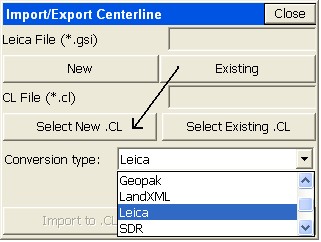
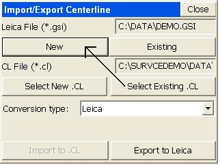
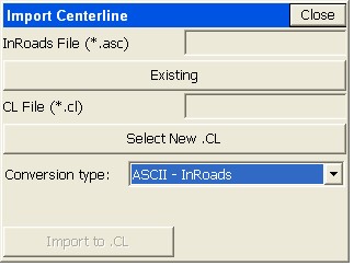
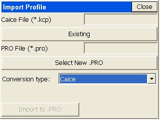
Clicking ōExistingö in the upper right will load the file and clicking ōSelect New .CLö will save the centerline file in the correct format for use in SurvCE. Reversing the direction, clicking ōSelect Existing .CLö would recall a SurvCE centerline file, and then clicking ōNewö in the upper left would save it back to a converted file, for use in other software.
For file types where both Import and Export options are available, the conversion procedure forms a ōcriss-crossö: You bring the files into SurvCE by going upper right (ōExistingö) to lower left (ōSelect Newö). You send the files back to the ōnon-SurvCEö format by going lower right (ōSelect Existingö) to upper left ōNewö as shown in the next figure.
When the files have been selected, the appropriate action is highlighted below. When the process is completed, the program announces ōProcess Done,ö and you are free to move on to the next command. Most formats only convert to SurvCE and not back again, and therefore only have ōone-wayö dialogs. These include ASCII-Inroads, ASCII-LDD, Geopak, Moss, TDS and Terramodel/Geodimeter. When only 1-way conversion (to SurvCE) is available.
If the SDR format is selected, the dialog automatically changes.
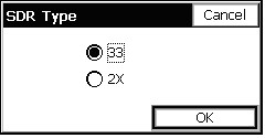
When the process is completed, the program announces ōProcess Done,ö and you are free to move on to the next command. Most formats only convert to SurvCE and not back again, and therefore only have ōone-wayö dialogs. These include ASCII-Inroads, ASCII-LDD, Geopak, Moss, TDS and Terramodel/Geodimeter. When only 1-way conversion (to SurvCE) is available, the dialog appears as shown in this figure.
Importing TDS RD5 Files
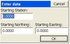
Importing TDS RD5 Files: If TDS is selected, centerlines can be converted ō1-wayö to SurvCE centerlines. It is important to note that the TDS RD5 file is a dual centerline and profile file. Because the TDS RD5 file does not display the starting station, an extra dialog will appear requesting starting coordinates and a starting station.
Verify the Conversion
It is recommended that after converting centerlines, profiles or cross section files to SurvCE format, that you go to the Input-Edit options for these file types, and review the data to verify that the correct file was converted and that the conversion was successful. So, for example, after converting a centerline from, say, Inroads format to SurvCE ō.clö format, go directly to Input-Edit Centerline in the Roads menu and verify that data.
Recognizing File Formats
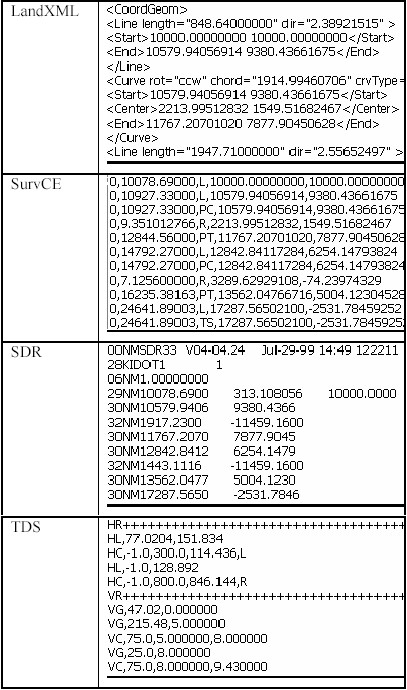
For reference, portions of four of the file types are shown below, as they might display in a Text Editor. The LandXML, SurvCE and SDR examples all reference the file DOT1.CL. These displays may help you recognize these file types in the future. The new LandXML format, endorsed by many Departments of Transportation in the United States, may soon become the standard in the future for internet transfer of roading and other types of design files.
Centerline Transformation
This routine is designed primarily to convert centerline data from Metric to Survey Feet or from Survey Feet to Metric. Here is the dialog, and scale factor, when converting from Metric to Survey Feet.
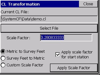
Apply scale factor for start station: If this option is clicked on, as shown, then a starting station of 1000, for example, would become a start station of 3280.833. If clicked off, the start station would remain at 1000. If the goal is to change the starting station by a certain amount unrelated to the scale factor, then you must use Input-Edit Centerline and enter a new start station in the initial dialog. This will automatically translate all stations in the centerline by the appropriate amount.
When ōApply Scale Factorö is selected, the centerline is adjusted by the scale factor, after a confirming ōwarningö screen.
Profile Conversion
This command converts vertical alignments to and from the Carlson profile format (*.PRO). Supported file types include:
The SurvCE format has a .PRO extension. These source files can be loaded into SurvCE using Data Transfer, located in the File menu options. The conversion screen is similar to Centerline Conversion, with the characteristic ōcriss-crossö logic for 2-way conversion (LandXML and Leica) and one-way conversion for the other options.
The SurvCE Profile ōfile formatö: It should be noted that of all the SurvCE file types that are ASCII and therefore viewable in text editors, the profile ō.proö file has the simplest format. The format is station, elevation, length of vertical curve, description for road profiles. For example, the Demo.pro file that is typically provided with the software has the following four lines (which can be viewed in Notepad):
0.0000, 997.0000 , 0.0000,
200.0000, 1005.0000 , 200.0000,
308.0000, 1003.9200 , 0.0000,
0.0, 0.0, 0.0 (this is an ōend-profileö line)
A profile, therefore, can be hand-entered within a text editor as well as officially made within SurvCE. Other ASCII file types such as centerlines can be deciphered, but are generally of a more complicated design and are best entered using the editors provided within SurvCE.
Profile Transformation
Like Centerline Transformation, this routine is primarily used to scale a profile up or down to go from Survey Feet to Metric or from Metric to Survey Feet.
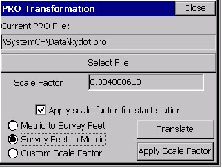
Unlike with Centerline Transformation, you can directly ōtranslateö the profile up or down, in addition to scaling the profile stationing and elevations. If you want to apply a translation to selected stations, tap the Translate button. The ōTranslateö option leads to its own dialog of entries, which allows you to translate both the stationing and the elevations, as shown below. In this way, you could make the starting station 1000, or raise the entire profile 15 feet or meters.
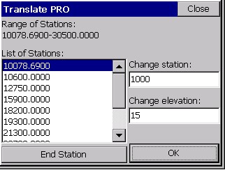
By default, the entire range of stations is selected as shown at the top [10078.69-30500.00]. If you wish to only translate a range, highlight the beginning station, then highlight the end station and tap the End Station button. Next enter the amount to translate in the Change Station box and optionally the amount of elevation to change. Tap OK when you are finished.
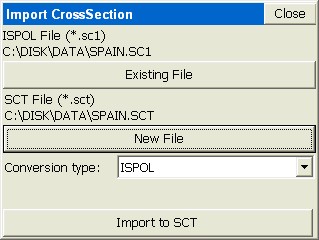
Section File Conversion
This command converts section files to and from the Carlson section file format (*.SCT). Supported file types include:
The SurvCE format is ō.SCTö. Section files are used for Slope Staking, Elevation Differance and Template Staking. Furthermore, Cross Section Survey has the ability to output section files.
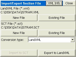
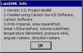
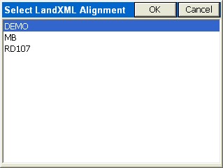
Note that if you click ōXML Infoö at the top of the screen, you’ll see some of the ōheaderö information associated with the XML file to be exported or imported.
To export to LandXML, you need to load a LandXML file that already contains a centerline covering all or part of the station range in the SCT cross section file. Otherwise, you will obtain an error message.
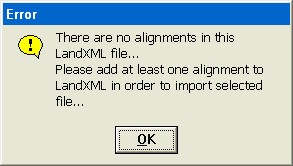
Despite the message, you can add the horizontal alignment portion to the LandXML file after creating the file with sections only. However, if you first create a LandXML file containing one or more alignments, then choose that existing LandXML file to export to, you can select among those centerline alignments when making the cross section file.
Note that some section file conversions are ōImport Onlyö, with the dialog appearing as follows:
Section files in SurvCE can contain descriptions useful for reference in Template Stakeout, for example. If descriptions are found in the source section file, they will be captured by the import process into the ō.sctö file for use in SurvCE.
Input-Edit Section File
This routine is a convenient cross section editor. It can be used for entering new sets of cross sections or simply for editing and reviewing an existing set of cross sections. One nice application is for Slope Staking. If you know the left and right ōpivot pointsö on stations to be slope staked, you can enter very simple, 2-point cross sections consisting of the left pivot offset and elevation and the right pivot offset and elevation. Then, without taking a ōcheat sheetö into the field, you can slope stake by cross section method, and the program will seek these pivot points, and even interpolate the correct pivot points between entered cross sections.
A better approach would be to include all break points in the sections from pivot left to pivot right, along with descriptions. Then Slope Staking would report the progressive information to grade each point from the catch all the way into centerline. This ōsection-based slope stakingö is a cross between user-defined (where you need the ōcheat sheetö!) and design files, where the pivot offsets and elevations are taken from the pivot points in the template as they react with the profile and superelevation files. Sections used in Template Stakeout should be complete cross section files, with all offsets, to enable precise, interpolated stakeout within the left-to-right range of the sections, on station, or at interpolated stations.
The Input-Edit Section File routine begins by prompting for a cross section file name. If you wish to start a new cross section file, just enter a new name.
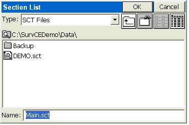
If you choose to select an existing cross section file, such as DEMO.sct, after selecting the file, you will see the ōSection Listö dialog.
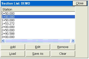
From this dialog, you can Add stations, Edit existing stations, Remove stations, Load entire new cross section files, Save As (to save your changes to the current loaded file or to a new cross section file) and lastly, you can Clear the list of stations (not recommended unless you want to start from scratch). Let’s select Edit and review a station.
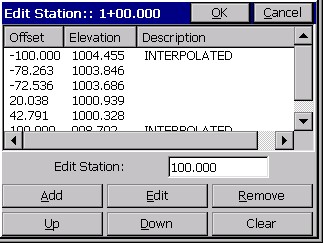
In this dialog, you can add offsets and elevations, edit existing offsets and elevations, remove them, move them up and down for sorting, and clear the list. Note also that cross section offsets are negative for left of centerline and positive for right of centerline, and can have descriptions such as SH, EOP, CL, Ditch, etc. These descriptions, where they exist, are potentially useful for description-based interpolation between stations, as applied in Template Stakeout. If you want to add an offset at -20.038 called EOP, click ōAddö. You don’t have to highlight the correct offset to add above — it will sort out and place the new entry appropriately.
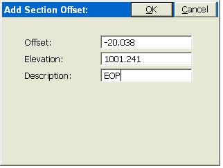
When you click OK, it will be in the list.
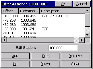
The Edit box leads to the same entry dialog as Add. Remove will provide a warning and then delete the highlighted offset and elevation. Up and Down should not be used unless a file conversion led to out-of-order listing of offsets and elevations. When you click OK from the station edit dialog, you can save the revised cross section file back in the section list dialog.
Input-Edit Superelevation
Roads can contain one or more curves, and each curve can have its own superelevation data: start station for super transition, station for full super, percent of full super, station for end full super and station for ending the super transition back to normal crown. In SurvCE, each superelevation data set for each curve would be entered as a ōlineö of superelevation data in the ō.supö file.
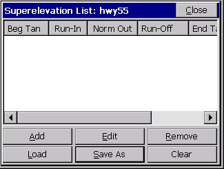
If we had two curves, both with superelevation, then we would do two ōAddsö off this dialog. Let’s say, for simplicity we have a road with a 2% ōnormal crownö which has 1 curve to the left followed by 1 curve to the right, with the following information:
|
Curve 1 |
Curve 2 |
|
|
Start Super Pivot |
Sta: 100 |
Sta: 2200 |
|
Full Super |
Sta: 600 |
Sta: 2500 |
|
Full Super %: |
3% Left |
4% Right |
|
End Super: |
Sta: 1400 |
Sta: 3500 |
|
End Super Pivot: |
Sta: 1900 |
Sta: 3800 |
The first curve to the left goes through three stages as it pivots into full super: (1) the right side pivots to ōflatö, (2) the right side pivots to ōreverse crownö, where the slope is the same across the template and (3) where both the right and left side pivot from the hinge point (centerline) into full super. All of these key pivot points are entered in the superelevation dialog.
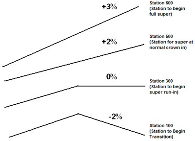
You enter all these key stations (begin, flat outside lane, reverse crown, full super) both going up to full super and transitioning back down to normal crown. Recognizing that the normal crown of -2% transitions from station 100 through a slope of 5%, the transition is 1% per 100 feet, assuming an even rate of transition. Therefore, a ōflatö outside slope occurs at station 300, reverse crown at station 500 and full super at station 600, as shown. You will need to compute these stations in advance. These intermediate stations are entered in the superelevation dialog to allow for different rates of transition from normal crown to flat to reverse crown to full super. Normally, the rates of transition are consistent. Note that super left or right is always entered as a positive percent slope — the road centerline curve direction will control the direction of pivot. You are now ready to click Add and enter in Curve 1.
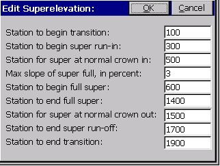
When we click OK, the first line of the superelevation dialog is filled in. Curve 1 is complete. Next, we enter Curve 2 as follows, using similar logic.
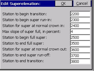
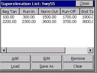
When OK is clicked, this leads to the completed two curves, and the summary dialog. There is one line (or row) for each curve.
Note: If any of the columns are too narrow to display all the text, you can ōgripö the vertical line separating columns, much like in programs such as Excel, and make the column wider.
The superelevation file is one of the optional ōroadingö or ōdesignö files in Slope Staking, Template Stakeout and Elevation Difference. After a superelevation file has been entered and saved, it will appear as the default superelevation file in both these commands, unless removed from the design file list by the user.
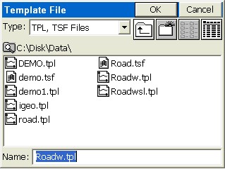
Input-Edit Template Series
SurvCE allows for two types of transitioning: (1) a single template can transition by being ōacted uponö by template transition files (made in Carlson Roads, Topsite, Leica Site Manager or SurvCADD) and superelevation files, or (2) a template series file can transition between several templates sharing identical IDs, but having different slopes and widths between ID points within the templates.
The Template Series approach can even be used to transition from normal crown to superelevation, avoiding the need to use superelevation files. The Template Series approach is commonly used to expand the width of a lane to accommodate, for example, a passing lane. Since template ID’s must match, if a ōspecial slopeö lane ōappearsö for a certain station range, then the Template Series approach can still be used as long as you add the extra ID point (e.g. EP2) to the normal template, perhaps making that point 0.001 units in dimension initially. In the second, transitional template, the EP2 lane can have the full width of 3.5 meters or 12 feet or whatever applies. If the transition starts at station 500 and ends at station 600, EP2, will be 1.75 meters or 6 feet or exactly half the full dimension at station 550.
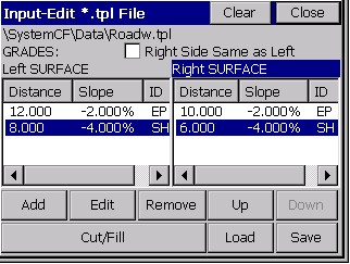
Starting with the demo.tpl file, with a 10’ lane to ID ōEPö followed by a 6’ shoulder lane to ID ōSHö, you can make another template called Road.tpl, with a 12’ lane to ōEPö and an 8’ shoulder to ōSHö. Note how we have made sure to use the same ID for the road lane (ōEPö) and the shoulder lane (ōSHö).
If the demo.tpl is used from station 0 to 500, and the RoadW.tpl is used from 600 to the end of the project at station 1000, then the entry process for a Template Series is as follows:
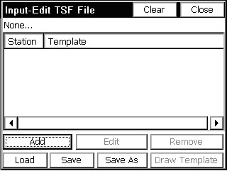
Click Add and you will obtain the next dialog.
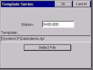
Choose Select File and pick the first template (demo.tpl). Click OK. Back in the main dialog, click Add again and specify the ending station for demo.tpl as station 500. Then click Add again and specify the first station for RoadW.tpl as station 600. You do not need to specify an end station, as RoadW.tpl will be used for the remainder of the project.
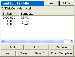
You then Save the Template Series File. When running Template Stakeout or Slope Staking and recalling a template file, you now have the option to recall a Template Series File and process a set of transitioning templates.