|
Job Settings (Stakeout)
|
|
Job Settings (Stakeout)
|
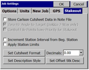
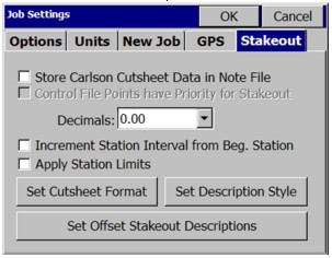
This command allows you to set configuration options for data collection. These options remain set from job to job. Some options may only apply to GPS or to Total Station use. If you are configured for total station, selecting the Stakeout tab will give you the options shown in the next figure (top). If you are configured for GPS, the Stakeout tab will appear, as shown at the figure below (bottom). If an option is not applicable, it is grayed out.
Note: Use this option with care. You may not realize that this option is set, and will discover that directions to your expected stakeout point of 10 are really based on a point 10 from another file altogether – the control file.
![]()
The Set Cutsheet Format button leads to the following three options:
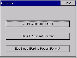
Set Pt Cutsheet Format: This button opens a Settings dialog where you can customize the Point Cutsheet report format as well as view and edit the current point cutsheet file. This applies to the command Stake Points.
Set Cl Cutsheet Format: This button opens a Settings dialog where you can customize the Centerline Cutsheet report format and view and edit the current centerline cutsheet file. This applies to commands within Stake Line/Arc, and to Offset Stakeout, Point Projection and Template Stakeout (in Roading) and includes station and offset options in the stored file, as well as cut/fill. A special ōcenterline-styleö cutsheet file, containing station and offset information, can be named and saved within the Roading command, Cross Section Survey. This file is viewable in the editor within Set Cl Cutsheet Format, but has no cut/fill values, just ōas-builtö data. Centerline-based cutsheets have more configurable options in the report, such as Stake Station, Staked Offset, Design Station and Design Offset. The Design Point ID is one of the configurable items to report, and since commands such as Offset Stakeout, Point Projection and Template Stakeout do not stake out Point ID’s, the program uses either the command name (CL for Stake Centerline, PP for Point Projection), offset reference, or template ID as the ōdesign point nameö. ōRCurbö, for example, would be the name given to the design point in Offset Stakeout for top of curb, right side. This might lead to a variety of ID names for the design point.
Set Slope Staking Report Format: This button opens a Settings dialog where you can customize the Slope Staking report format as well as view and edit the current slope staking report file. This applies only to the command Slope Staking available with Roading. Slope Stake Cutsheets have an extra option to ōInclude progressive offsets reportö, and also has different options such as ōPivot Offsetö , ōSlope Ratioö and ōElevation: PP/CPö (Elevation of Pivot Point and/or Offset Point). Note that columns can serve a ōdual purposeö in the slope stake report. If progressive offsets are turned on, the header lines (such as Design Station) are ōignoredö for the additional information, and you obtain the incremental, delta distance and elevation from each point on the section or template from the offset stake to the ōcatchö and then all the way into centerline.
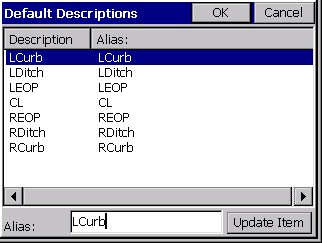
These last three options allow you to customize the respective output report. To change an item label, highlight the item, change the Header Label field, then tap Update Item. You can select an item in the list and turn it ON or OFF (no reporting). You can also control the order of the report items by using the Move Down and Move Up buttons. Changes must be made prior to starting a new cutsheet file. The Point Cutsheet, which applies to Stakeout Point, might be configured as shown below:
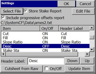
Select File: Tap this button to select the output file. The file name is shown below this button.
Include progressive offset reports:
Store Pt Cutsheet File: Check this toggle to store the report to the selected file. Uncheck this toggle to disable the report.
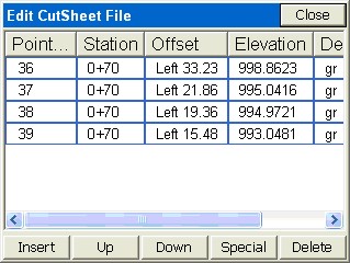
Edit File: Click to Edit and review the cutsheet file. Here is a point cutsheet file. Notice that the vertical bars of the ōspreadsheetö can be moved left and right condensing the display, to see more of the header lines. Just pick them in the title line and move them. Shown below is a Point Cutsheet, as viewed in the Edit File option.
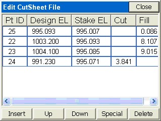
The Cutsheet editor includes the ability to insert and delete lines. If you insert a line and enter a Design Elevation and a Stake Elevation, the program will compute the cut or fill. Using the ōSpecialö button, you can increase or decrease the Pt ID, Design Elevation or Stake Elevation by any desired amount, and the cut or fill will be computed. Do not use the ōSpecialö button to directly modify the cut or fill.
Header Label: You can substitute header text of your own choice for the defaults. Here, the text Pt ID was substituted for Design Pt#. Tap Update Item after changing a Header Label. These changes should be done prior to starting a new cutsheet file—they cannot be applied retroactively to a file that already contains information. However, the header line in that file (eg. Market.txt) can always be edited using Notepad or any text editor to accomplish the change.
Down-Up: Items in the list can be moved up and down to change their order. For example, if you prefer Fill before Cut in the report, just move Cut down below Fill.
Cutsheet from Raw: SurvCE automatically stores cutsheet data and header information to the raw file for the job. You can capture and report the cutsheet information direct from the raw file. Before doing this, it is recommended that you start a new cutsheet file, configure the header lines and order of information as desired, then run ōCutsheet from Rawö.
The very act of storing a staked point is optional. You can stake a point or a station and offset, but must click ōStore Pointö within the stakeout screens to actually store a point. But if you do store the point, the description is configurable.
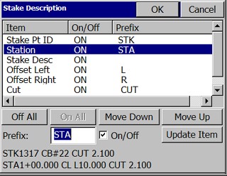
A user in Australia or Great Britain might want to change the STA for ōStationö to CH for ōChainageö. An example of a typical stake description, based on your configuration settings, is shown at the bottom left of the screen. The first line (STK1317 CB#22 CUT 2.100) represents a typical Stake Point description, where CB#22 is the description you would enter, and the rest is governed by your Stake Description settings. Similarly, if centerline-based stakeout is being conducted, then the lower line would apply. The description (CL in this case) is the only aspect entered by the user in the field during stakeout. All the rest is reported based on your Stake Description settings. If you turn off an item, note how it will not appear in the reported ōsampleö description. The ō+ö in the station can also be configured to appear or not appear, but this is set globally within the Units Tab of Job Settings. The behavior of the On/Off, Up/Down and Update buttons is identical to that discussed above in the Cutsheet discussion.
Other routines, particularly Cross Section Survey and Slope Staking (part of the Roading features), have their own settings for descriptions. When any automatic description for stakeout is turned on, the program will no longer default to the last-entered description: it will use the ōautomaticö description instead. If you type a new description, you will turn off the ōautomaticö stakeout description. If you delete the default (new) description, the program will return to using the automatic stakeout description. To delete, you can simply place the cursor in the description field and hit the delete key — there is no need to first highlight the description.
This option allows users to define the preset description values for the defined offset points used in the Offset Stakeout routine.